
Civil Engineering
GATE CE format:nat PYQs
Build your understanding with focused practice from past exam papers.
Questions 461–470 of 495. Imported answers require independent review unless marked reviewed.
Question 38
Open questionCE-2NAT2 marksNeeds review
Two towers, A and B, standing vertically on a horizontal ground, appear in a vertical aerial photograph as shown in the figure.
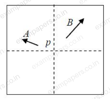
The length of the image of the tower A on the photograph is 1.5 cm and of the tower B is 2.0 cm. The distance of the top of the tower A (as shown by the arrowhead) is 4.0 cm and the distance of the top of the tower B is 6.0 cm, as measured from the principal point
of the photograph. If the height of the tower B is 80 m, the height (in meters) of the tower A isLog in to check the answer
You can attempt this question now. Sign in to view the answer key, explanations and discussion.Log in to check answerQuestion 39
Open questionCENAT2 marksNeeds review
Consider the stepped bar made with a linear elastic material and subjected to an axial load of 1 kN, as shown in the figure.
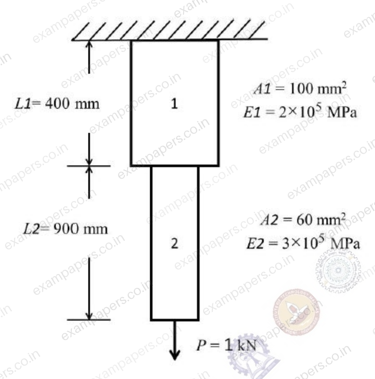
Segments 1 and 2 have cross-sectional area of 100 mm
and 60 mm
, Young’s modulus of 2×10
MPa and 3×10
MPa, and length of 400 mm and 900 mm, respectively. The strain energy (in N-m, up to one decimal place) in the bar due to the axial load isLog in to check the answer
You can attempt this question now. Sign in to view the answer key, explanations and discussion.Log in to check answerQuestion 39
Open questionCE-2NAT2 marksNeeds review
A hollow circular shaft has an outer diameter of 100 mm and inner diameter of 50 mm. If the allowable shear stress is 125 MPa, the maximum torque (in kN-m) that the shaft can resist is
Log in to check the answer
You can attempt this question now. Sign in to view the answer key, explanations and discussion.Log in to check answerQuestion 40
Open questionCENAT2 marksNeeds review
The value of M in the beam ABC shown in the figure is such that the joint B does not rotate.
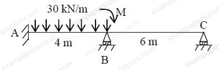
The value of support reaction (in kN) at B should be equal to
Log in to check the answer
You can attempt this question now. Sign in to view the answer key, explanations and discussion.Log in to check answerQuestion 40
Open questionCE-2NAT2 marksNeeds review
A simply supported rectangular concrete beam of span 8 m has to be prestressed with a force of 1600 kN. The tendon is of parabolic profile having zero eccentricity at the supports. The beam has to carry an external uniformly distributed load of intensity 30 kN/m. Neglecting the self-weight of the beam, the maximum dip (in meters, up to two decimal places) of the tendon at the mid-span to balance the external load should be
Log in to check the answer
You can attempt this question now. Sign in to view the answer key, explanations and discussion.Log in to check answerQuestion 41
Open questionCENAT2 marksNeeds review
Consider the beam ABCD shown in the figure.

AB = BC = 4 m; CD = 10 m. For a moving concentrated load of 50 kN on the beam, the magnitude of the maximum bending moment (in kN-m) obtained at the support C will be equal to
Log in to check the answer
You can attempt this question now. Sign in to view the answer key, explanations and discussion.Log in to check answerQuestion 41
Open questionCE-2NAT2 marksNeeds review
Two plates of 8 mm thickness each are connected by a fillet weld of 6 mm thickness as shown in the figure.
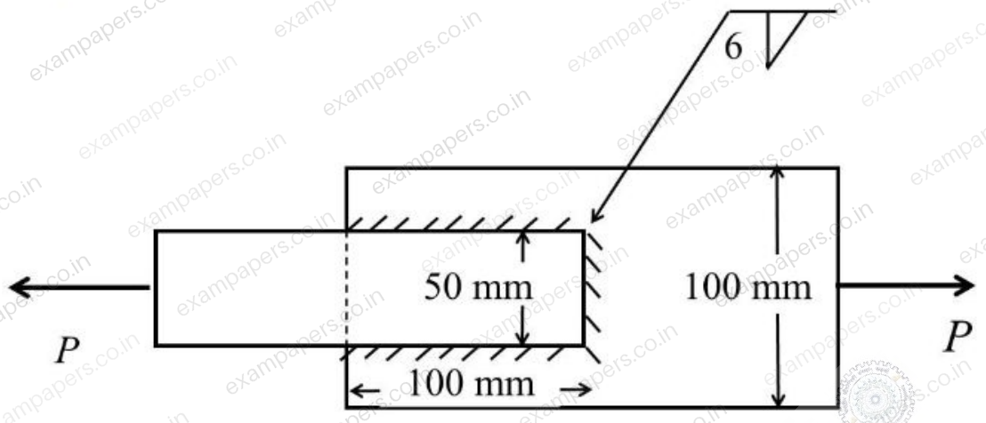
The permissible stresses in the plate and the weld are 150 MPa and 110 MPa, respectively. Assuming the length of the weld shown in the figure to be the effective length, the permissible load
(in kN) isLog in to check the answer
You can attempt this question now. Sign in to view the answer key, explanations and discussion.Log in to check answerQuestion 42
Open questionCENAT2 marksNeeds review
Consider two axially loaded columns, namely, 1 and 2, made of a linear elastic material with Young’s modulus 2×10
MPa, square cross-section with side 10 mm, and length 1 m. For Column 1, one end is fixed and the other end is free. For Column 2, one end is fixed and the other end is pinned. Based on the Euler’s theory, the ratio (up to one decimal place) of the buckling load of Column 2 to the buckling load of Column 1 isLog in to check the answer
You can attempt this question now. Sign in to view the answer key, explanations and discussion.Log in to check answerQuestion 42
Open questionCE-2NAT2 marksNeeds review
Consider the portal frame shown in the figure and assume the modulus of elasticity,
MPa and the moment of inertia,
mm
for all the members of the frame. 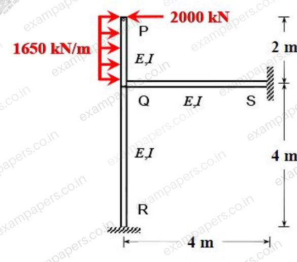
The rotation (in degrees, up to one decimal place) at the rigid joint Q would be
Log in to check the answer
You can attempt this question now. Sign in to view the answer key, explanations and discussion.Log in to check answerQuestion 43
Open questionCENAT2 marksNeeds review
A column is subjected to a load through a bracket as shown in the figure.
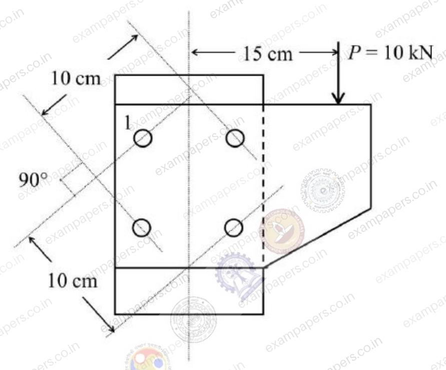
The resultant force (in kN, up to one decimal place) in the bolt 1 is
Log in to check the answer
You can attempt this question now. Sign in to view the answer key, explanations and discussion.Log in to check answer