
Civil Engineering
GATE CE topic:structural-analysis PYQs
Build your understanding with focused practice from past exam papers.
Questions 41–50 of 65. Imported answers require independent review unless marked reviewed.
Question 5
Open questionCEMCQ1 markNeeds review
Consider the planar truss shown in the figure (not drawn to the scale)
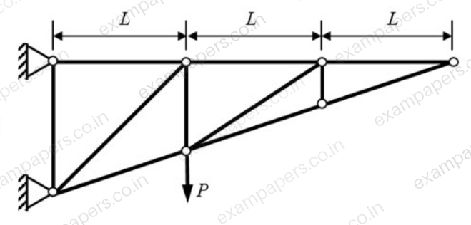
Neglecting self-weight of the members, the number of zero-force members in the truss under the action of the load
, isYour answerChoose one option.
Log in to check the answer
You can attempt this question now. Sign in to view the answer key, explanations and discussion.Log in to check answerQuestion 19
Open questionCENAT1 markNeeds review
A planar elastic structure is subjected to uniformly distributed load, as shown in the figure
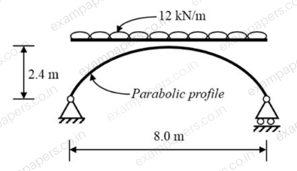
(not drawn to the scale)
Neglecting self-weight, the maximum bending moment generated in the structure (in kN.m, round off to the nearest integer), is ________.
Log in to check the answer
You can attempt this question now. Sign in to view the answer key, explanations and discussion.Log in to check answerQuestion 28
Open questionCEMCQ2 marksNeeds review
Distributed load(s) of 50 kN/m may occupy any position(s) (either continuously or in patches) on the girder PQRST as shown in the figure (not drawn to the scale). The maximum negative (hogging) bending moment (in kN.m) that occurs at point R, is
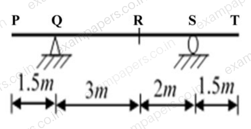
Your answerChoose one option.
Log in to check the answer
You can attempt this question now. Sign in to view the answer key, explanations and discussion.Log in to check answerQuestion 29
Open questionCEMCQ2 marksNeeds review
The planar structure RST shown in the figure
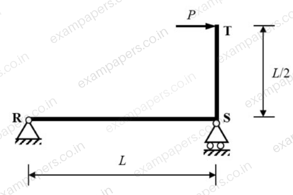
is roller-supported at S and pin-supported at R. Members RS and ST have uniform flexural rigidity
and S is a rigid joint. Consider only bending deformation and neglect effects of self-weight and axial stiffness.When the structure is subjected to a concentrated horizontal load
at the end T, the magnitude of rotation at the support R, isYour answerChoose one option.
Log in to check the answer
You can attempt this question now. Sign in to view the answer key, explanations and discussion.Log in to check answerQuestion 30
Open questionCEMCQ2 marksNeeds review
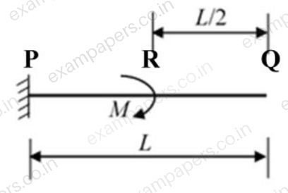
A cantilever beam PQ of uniform flexural rigidity (EI) is subjected to a concentrated moment M at R as shown in the figure. The deflection at the free end Q is
Your answerChoose one option.
Log in to check the answer
You can attempt this question now. Sign in to view the answer key, explanations and discussion.Log in to check answerQuestion 30
Open questionCEMCQ2 marksNeeds review
Joints I, J, K, L, Q and M of the frame shown in the figure
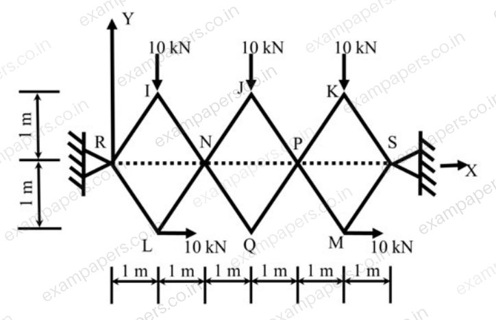
(not drawn to the scale) are pins. Continuous members IQ and LJ are connected through a pin at N. Continuous members JM and KQ are connected through a pin at P. The frame has hinge supports at joints R and S. The loads acting at joints I, J and K are along the negative Y direction and the loads acting at joints L and M are along the positive X direction.
The magnitude of the horizontal component of reaction (in kN) at S, is
Your answerChoose one option.
Log in to check the answer
You can attempt this question now. Sign in to view the answer key, explanations and discussion.Log in to check answerQuestion 42
Open questionCENAT2 marksNeeds review
The plane truss has hinge supports at P and W and is subjected to the horizontal forces as shown in the figure (not drawn to scale).
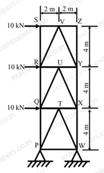
Representing the tensile force with ‘+’ sign and the compressive force with ‘−’ sign, the force in member XW (in kN, round off to the nearest integer), is _____.
Log in to check the answer
You can attempt this question now. Sign in to view the answer key, explanations and discussion.Log in to check answerQuestion 5
Open questionCEMCQ1 markNeeds review
A plane truss is shown in the figure (not drawn to scale).
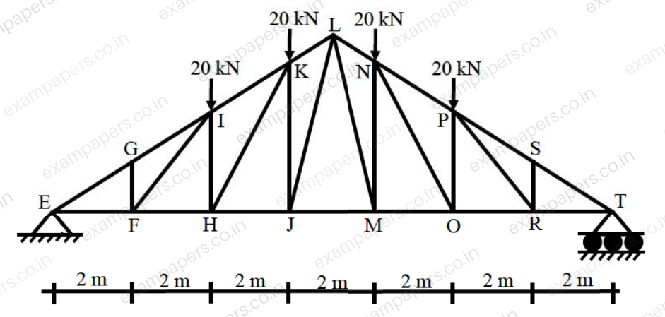
Which one of the options contains ONLY zero force members in the truss?
Your answerChoose one option.
Log in to check the answer
You can attempt this question now. Sign in to view the answer key, explanations and discussion.Log in to check answerQuestion 7
Open questionCEMCQ1 markNeeds review
Consider the pin-jointed plane truss shown in the figure (not drawn to scale). Let
,
, and
denote the vertical reactions (upward positive) applied by the supports at P, Q, and R respectively, on the truss. The correct combination of
is represented by 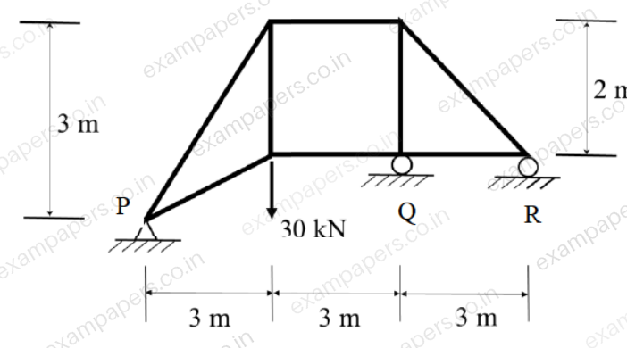
Your answerChoose one option.
Log in to check the answer
You can attempt this question now. Sign in to view the answer key, explanations and discussion.Log in to check answerQuestion 20
Open questionCENAT1 markNeeds review
The degree of static indeterminacy of the plane frame as shown in the figure is ______
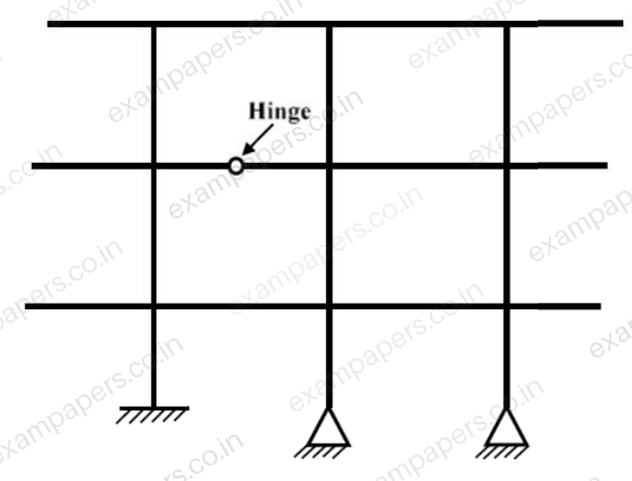
Log in to check the answer
You can attempt this question now. Sign in to view the answer key, explanations and discussion.Log in to check answer