
Electronics and Communication Engineering
GATE ECE branch:ec PYQs
Build your understanding with focused practice from past exam papers.
Questions 661–670 of 715. Imported answers require independent review unless marked reviewed.
Question 38
Open questionECMCQ2 marksNeeds review
Two
-channel MOSFETs, T1 and T2, are identical in all respects except that the width of T2 is double that of T1. Both the transistors are biased in the saturation region of operation, but the gate overdrive voltage (
) of T2 is double that of T1, where
and
are the gate-to-source voltage and threshold voltage of the transistors, respectively. If the drain current and transconductance of T1 are
and
, respectively, the corresponding values of these two parameters for T2 areYour answerChoose one option.
Log in to check the answer
You can attempt this question now. Sign in to view the answer key, explanations and discussion.Log in to check answerQuestion 39
Open questionECNAT2 marksNeeds review
In the figure shown, the
transistor acts as a switch. 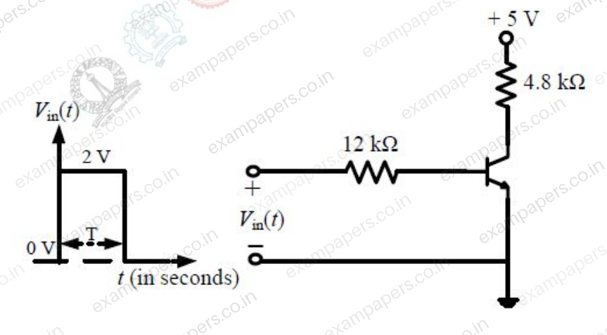
For the input
as shown in the figure, the transistor switches between the cut-off and saturation regions of operation, when T is large. Assume collector-to-emitter voltage at saturation
and base-to-emitter voltage
. The minimum value of the common-base current gain (
) of the transistor for the switching should be ________.Log in to check the answer
You can attempt this question now. Sign in to view the answer key, explanations and discussion.Log in to check answerQuestion 39
Open questionECMCQ2 marksNeeds review
An abrupt
junction (located at
) is uniformly doped on both
and
sides. The width of the depletion region is
and the electric field variation in the
-direction is
. Which of the following figures represents the electric field profile near the
junction?Your answerChoose one option.
Log in to check the answer
You can attempt this question now. Sign in to view the answer key, explanations and discussion.Log in to check answerQuestion 40
Open questionECNAT2 marksNeeds review
For the circuit shown, assume that the NMOS transistor is in saturation. Its threshold voltage
and its transconductance parameter
. Neglect channel length modulation and body bias effects. Under these conditions, the drain current
in mA is ____________. 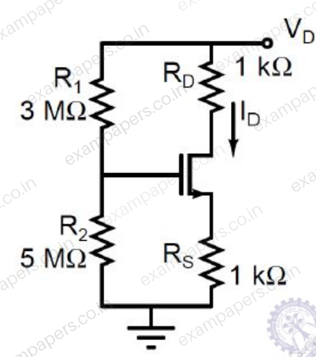
Log in to check the answer
You can attempt this question now. Sign in to view the answer key, explanations and discussion.Log in to check answerQuestion 40
Open questionECMCQ2 marksNeeds review
Assuming that transistors M1 and M2 are identical and have a threshold voltage of 1 V, the state of transistors M1 and M2 are respectively
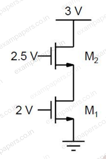
Your answerChoose one option.
Log in to check the answer
You can attempt this question now. Sign in to view the answer key, explanations and discussion.Log in to check answerQuestion 41
Open questionECNAT2 marksNeeds review
For the DC analysis of the Common-Emitter amplifier shown, neglect the base current and assume that the emitter and collector currents are equal. Given that
,
, and the BJT output resistance
is practically infinite. Under these conditions, the midband voltage gain magnitude,
, is ____________. 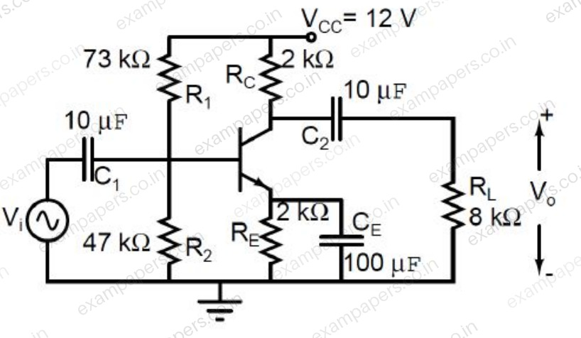
Log in to check the answer
You can attempt this question now. Sign in to view the answer key, explanations and discussion.Log in to check answerQuestion 41
Open questionECNAT2 marksNeeds review
In the circuit shown, transistors Q1 and Q2 are biased at a collector current of 2.6 mA. Assuming that transistor current gains are sufficiently large to assume collector current equal to emitter current and thermal voltage of 26 mV, the magnitude of voltage gain
in the mid-band frequency range is ______ (up to second decimal place). 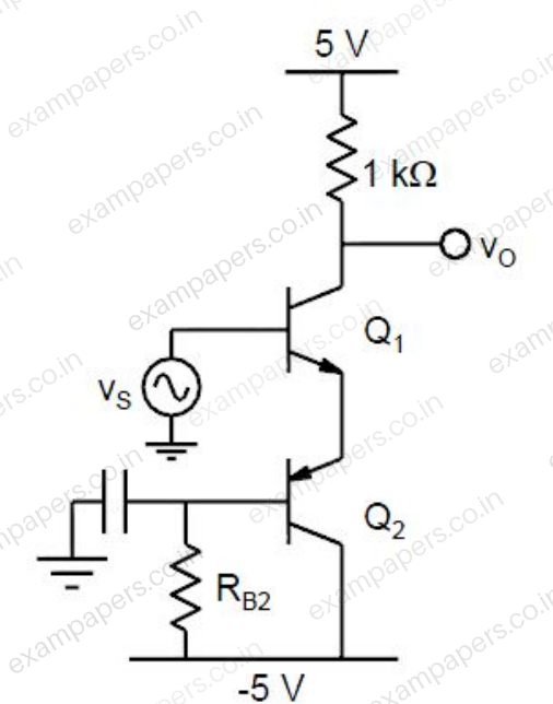
Log in to check the answer
You can attempt this question now. Sign in to view the answer key, explanations and discussion.Log in to check answerQuestion 42
Open questionECNAT2 marksNeeds review
The amplifier circuit shown in the figure is implemented using a compensated operational amplifier (op-amp), and has an open-loop voltage gain,
and an open-loop cut-off frequency,
. The voltage gain of the amplifier at 15 kHz, in V/V, is ____________. 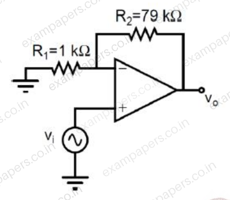
Log in to check the answer
You can attempt this question now. Sign in to view the answer key, explanations and discussion.Log in to check answerQuestion 42
Open questionECNAT2 marksNeeds review
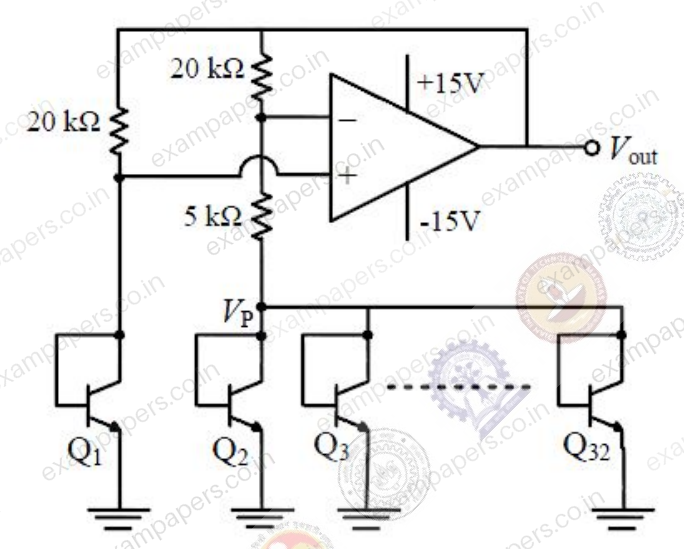
In the voltage reference circuit shown in the figure, the op-amp is ideal and the transistors Q₁, Q₂, ..., Q₃ are identical in all respects and have infinitely large values of common-emitter current gain (β). The collector current (
) of the transistors is related to their base-emitter voltage (
) by the relation
, where
is the saturation current. Assume that the voltage
shown in the figure is 0.7 V and the thermal voltage
. 
The output voltage
(in volts) is ______Log in to check the answer
You can attempt this question now. Sign in to view the answer key, explanations and discussion.Log in to check answerQuestion 43
Open questionECMCQ2 marksNeeds review
Which one of the following gives the simplified sum of products expression for the Boolean function
, where
,
,
and
are minterms corresponding to the inputs
,
and
with
as the MSB and
as the LSB?Your answerChoose one option.
Log in to check the answer
You can attempt this question now. Sign in to view the answer key, explanations and discussion.Log in to check answer