
Electronics and Communication Engineering
GATE ECE Circuit analysis PYQs
Build your understanding with focused practice from past exam papers.
How to practice Circuit analysis
Attempt a question, record the concept and assumptions, then check the available answer. Rework mistakes after revising the relevant concepts. Topic tags can overlap; review the question context.
Questions 1–10 of 50. Imported answers require independent review unless marked reviewed.
Question 13
Open questionECMCQ1 markNeeds review
The Laplace Transform of the signal
is given by which of the following expressions?[“*” represents convolution operator]
Your answerChoose one option.
Log in to check the answer
You can attempt this question now. Sign in to view the answer key, explanations and discussion.Log in to check answerQuestion 23
Open questionECMCQ1 markNeeds review
The relation between the input current (I) and the output voltage (V) of a circuit is governed by the equation:
. The circuit is excited by
, where q is a real valued constant. At
is
.Which of the following is an equivalent representation of the above case?
Your answerChoose one option.
Log in to check the answer
You can attempt this question now. Sign in to view the answer key, explanations and discussion.Log in to check answerQuestion 30
Open questionECNAT1 markNeeds review
The output voltage
(in Volt) for the network given in the Figure is __. (rounded off to two decimal places) 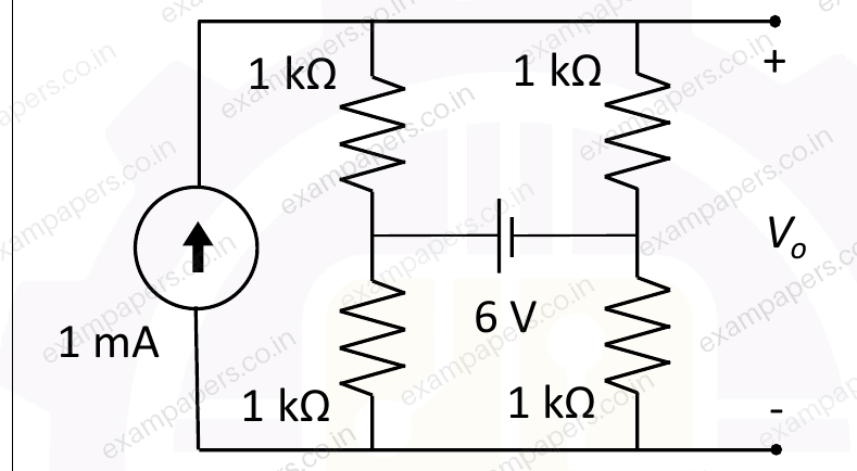
Log in to check the answer
You can attempt this question now. Sign in to view the answer key, explanations and discussion.Log in to check answerQuestion 31
Open questionECNAT1 markNeeds review
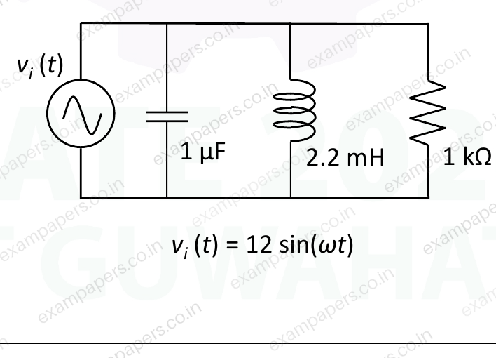
Consider the circuit shown in the Figure, where the input
is in Volt. The average power (in mW) dissipated in the load resistance of 1 kΩ at the resonant frequency is __. (rounded off to two decimal places) The circuit is driven by
. 
Log in to check the answer
You can attempt this question now. Sign in to view the answer key, explanations and discussion.Log in to check answerQuestion 39
Open questionECMCQ2 marksNeeds review
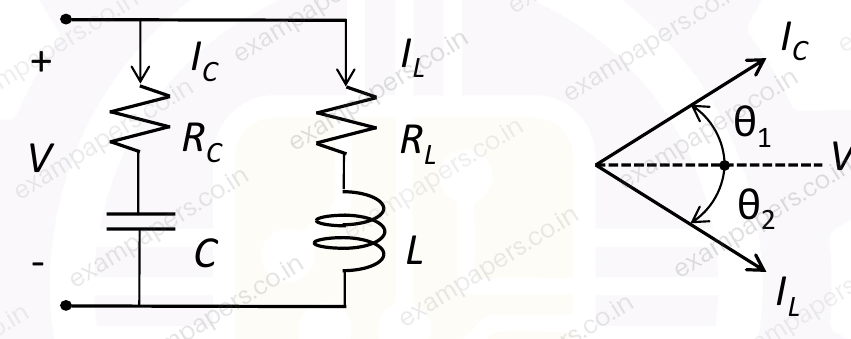
In the given circuit,
and
. The phasor diagram for
and
is also shown. Assume that the phase
is
at a frequency of 159.15 kHz. Among the following options, what is the nearest integer value of
? 
Your answerChoose one option.
Log in to check the answer
You can attempt this question now. Sign in to view the answer key, explanations and discussion.Log in to check answerQuestion 51
Open questionECMCQ2 marksNeeds review
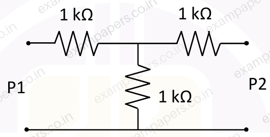
Consider the two-port network as shown in the Figure.
Which of the following options provides the correct set of values of A, B, C and D parameters?
Your answerChoose one option.
Log in to check the answer
You can attempt this question now. Sign in to view the answer key, explanations and discussion.Log in to check answerQuestion 19
Open questionECMCQ1 markNeeds review
Consider a part of an electrical network as shown below. Some node voltages, and the current flowing through the
resistor are as indicated. The voltage (in Volts) at node
is _____. 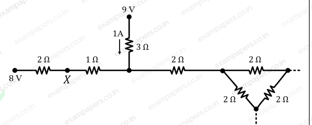
Your answerChoose one option.
Log in to check the answer
You can attempt this question now. Sign in to view the answer key, explanations and discussion.Log in to check answerQuestion 20
Open questionECMCQ1 markNeeds review
Let
,
, and
be the currents flowing through the capacitor, inductor, and resistor, respectively, in the circuit given below. The AC admittances are given in Siemens (S). Which one of the following is TRUE? 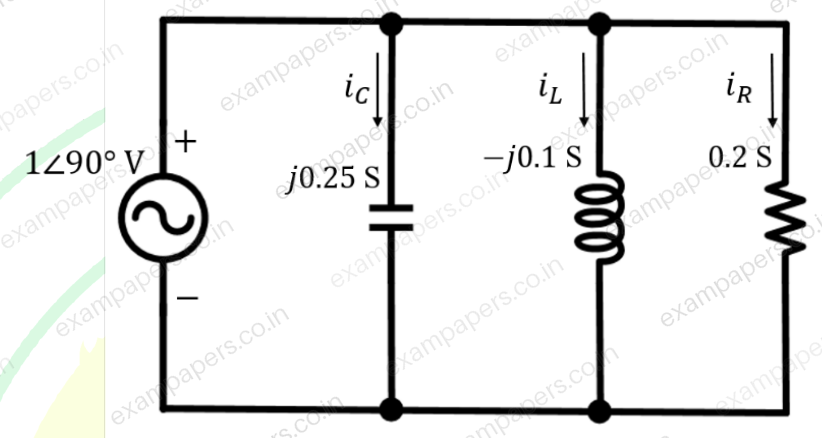
Your answerChoose one option.
Log in to check the answer
You can attempt this question now. Sign in to view the answer key, explanations and discussion.Log in to check answerQuestion 39
Open questionECMCQ2 marksNeeds review
In the circuit below,
is an ideal AC voltmeter and
is an ideal AC ammeter. The source voltage (in Volts) is
.What should be the value of the variable capacitor
such that the RMS readings on
and
are 25 V and 5 A, respectively? 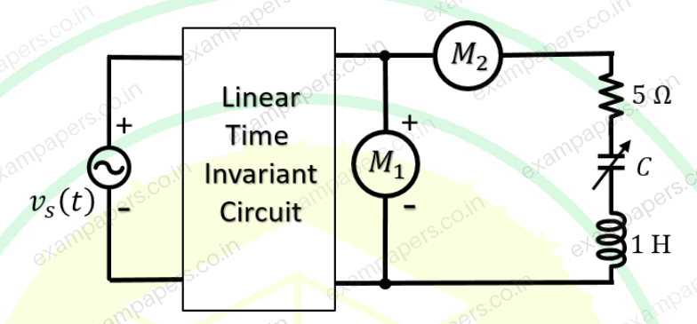
Your answerChoose one option.
Log in to check the answer
You can attempt this question now. Sign in to view the answer key, explanations and discussion.Log in to check answerQuestion 40
Open questionECMCQ2 marksNeeds review
The
-parameter matrix of a two port network relates the port voltages and port currents as follows:
The
-parameter matrix (with each entry in Ohms) of the network shown below is ________. 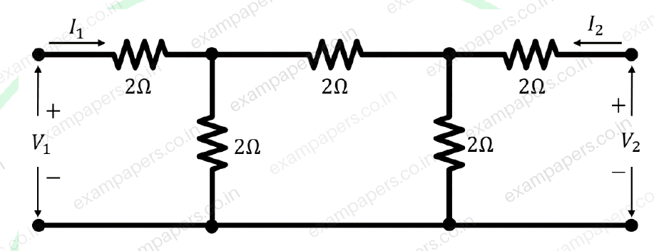
Your answerChoose one option.
Log in to check the answer
You can attempt this question now. Sign in to view the answer key, explanations and discussion.Log in to check answer