
Electronics and Communication Engineering
GATE ECE exam:gate PYQs
Build your understanding with focused practice from past exam papers.
Questions 531–540 of 715. Imported answers require independent review unless marked reviewed.
Question 1
Open questionECMCQ1 markNeeds review
Two identical MOS transistors M₁ and M₂ are connected as shown below. The circuit is used as an amplifier with the input connected between G and S terminals and the output taken between D and S terminals. V_bias and V_D are so adjusted that both transistors are in saturation. The transconductance of this combination is defined as
while the output resistance is
, where i_D is the current flowing into the drain of M₂. Let g_m₁, g_m₂ be the transconductances and r_o₁, r_o₂ be the output resistances of transistors M₁ and M₂, respectively.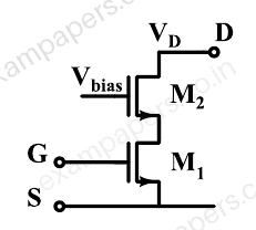
Which of the following statements about estimates for g_m and r_o is correct?
Your answerChoose one option.
Log in to check the answer
You can attempt this question now. Sign in to view the answer key, explanations and discussion.Log in to check answerQuestion 2
Open questionECMCQ1 markNeeds review
In the circuit shown below, the op-amp is ideal and Zener voltage of the diode is 2.5 volts. At the input, unit step voltage is applied, i.e.
volts. Also, at t = 0, the voltage across each of the capacitors is zero.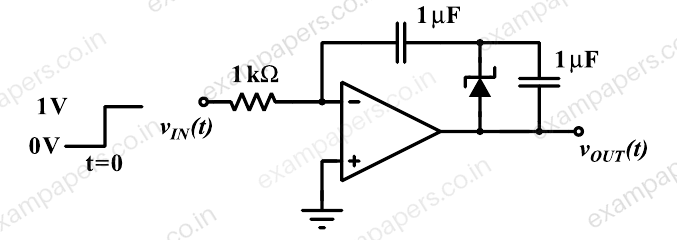
The time t, in milliseconds, at which the output voltage v_OUT crosses −10 V is
Your answerChoose one option.
Log in to check the answer
You can attempt this question now. Sign in to view the answer key, explanations and discussion.Log in to check answerQuestion 3
Open questionECMCQ1 markNeeds review
A good transimpedance amplifier has
Your answerChoose one option.
Log in to check the answer
You can attempt this question now. Sign in to view the answer key, explanations and discussion.Log in to check answerQuestion 4
Open questionECMCQ1 markNeeds review
Let the input be
and the output be
of a system, and the other parameters are real constants. Identify which among the following systems is not a linear system:Your answerChoose one option.
Log in to check the answer
You can attempt this question now. Sign in to view the answer key, explanations and discussion.Log in to check answerQuestion 5
Open questionECMCQ1 markNeeds review
The Nyquist stability criterion and the Routh criterion both are powerful analysis tools for determining the stability of feedback controllers. Identify which of the following statements is FALSE:
Your answerChoose one option.
Log in to check the answer
You can attempt this question now. Sign in to view the answer key, explanations and discussion.Log in to check answerQuestion 6
Open questionECMCQ1 markNeeds review
Consider p(s) = s³ + a₂s² + a₁s + a₀ with all real coefficients. It is known that its derivative p′(s) has no real roots. The number of real roots of p(s) is
Your answerChoose one option.
Log in to check the answer
You can attempt this question now. Sign in to view the answer key, explanations and discussion.Log in to check answerQuestion 7
Open questionECMCQ1 markNeeds review
In a p-n junction diode at equilibrium, which one of the following statements is NOT TRUE?
Your answerChoose one option.
Log in to check the answer
You can attempt this question now. Sign in to view the answer key, explanations and discussion.Log in to check answerQuestion 8
Open questionECMCQ1 markNeeds review
The logic function
realized by the given circuit is 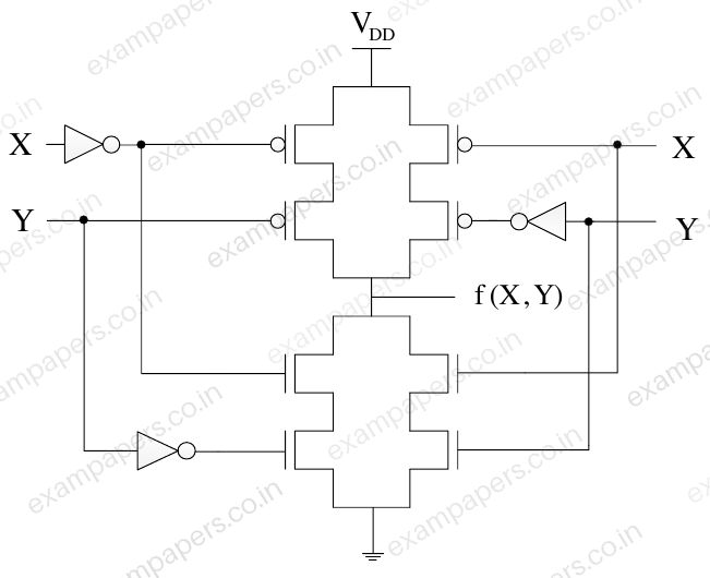
Your answerChoose one option.
Log in to check the answer
You can attempt this question now. Sign in to view the answer key, explanations and discussion.Log in to check answerQuestion 9
Open questionECMCQ1 markNeeds review
A function
defined by three Boolean variables A, B and C when expressed as sum of products is given by
, where,
,
, and
are the complements of the respective variables. The product of sums (POS) form of the function F isYour answerChoose one option.
Log in to check the answer
You can attempt this question now. Sign in to view the answer key, explanations and discussion.Log in to check answerQuestion 10
Open questionECMCQ1 markNeeds review
The points P, Q, and R shown on the Smith chart (normalized impedance chart) in the following figure represent:
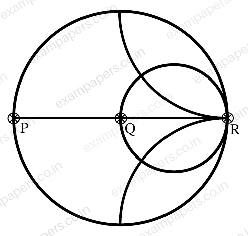
Your answerChoose one option.
Log in to check the answer
You can attempt this question now. Sign in to view the answer key, explanations and discussion.Log in to check answer