
Electronics and Communication Engineering
GATE ECE format:mcq PYQs
Build your understanding with focused practice from past exam papers.
Questions 181–190 of 426. Imported answers require independent review unless marked reviewed.
Question 16
Open questionECMCQ1 markNeeds review
Consider a long rectangular bar of direct bandgap
-type semiconductor. The equilibrium hole density is
and the intrinsic carrier concentration is
. Electron and hole diffusion lengths are
and
, respectively.The left side of the bar (
) is uniformly illuminated with a laser having photon energy greater than the bandgap of the semiconductor. Excess electron-hole pairs are generated ONLY at
because of the laser. The steady state electron density at
is
due to laser illumination. Under these conditions and ignoring electric field, the closest approximation (among the given options) of the steady state electron density at
is _________.Your answerChoose one option.
Log in to check the answer
You can attempt this question now. Sign in to view the answer key, explanations and discussion.Log in to check answerQuestion 17
Open questionECMCQ1 markNeeds review
In a non-degenerate bulk semiconductor with electron density
, the value of
, where
and
denote the bottom of the conduction band energy and electron Fermi level energy, respectively. Assume thermal voltage as
and the intrinsic carrier concentration is
. For
, the closest approximation of the value of
, among the given options, is _________.Your answerChoose one option.
Log in to check the answer
You can attempt this question now. Sign in to view the answer key, explanations and discussion.Log in to check answerQuestion 18
Open questionECMCQ1 markNeeds review
Consider the CMOS circuit shown in the figure (substrates are connected to their respective sources). The gate width (
) to gate length (
) ratios (
) of the transistors are as shown. Both the transistors have the same gate oxide capacitance per unit area. For the
MOSFET, the threshold voltage is
and the mobility of holes is
. For the
MOSFET, the threshold voltage is
and the mobility of electrons is
. The steady state output voltage
is _________. 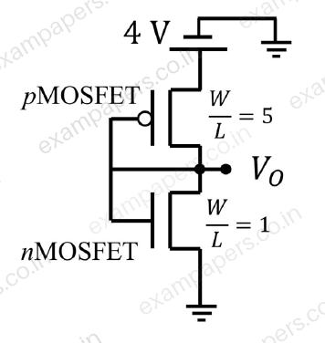
Your answerChoose one option.
Log in to check the answer
You can attempt this question now. Sign in to view the answer key, explanations and discussion.Log in to check answerQuestion 19
Open questionECMCQ1 markNeeds review
Consider the 2-bit multiplexer (MUX) shown in the figure. For OUTPUT to be the XOR of C and D, the values for
,
,
, and
are ____________. 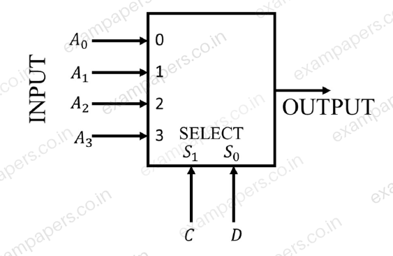
Your answerChoose one option.
Log in to check the answer
You can attempt this question now. Sign in to view the answer key, explanations and discussion.Log in to check answerQuestion 20
Open questionECMCQ1 markNeeds review
The ideal long channel
MOSFET and
MOSFET devices shown in the circuits have threshold voltages of 1 V and
V, respectively. The MOSFET substrates are connected to their respective sources. Ignore leakage currents and assume that the capacitors are initially discharged. For the applied voltages as shown, the steady state voltages are ________________. 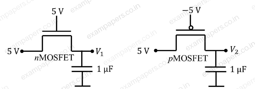
Your answerChoose one option.
Log in to check the answer
You can attempt this question now. Sign in to view the answer key, explanations and discussion.Log in to check answerQuestion 21
Open questionECMCQ1 markNeeds review
Consider a closed-loop control system with unity negative feedback and
in the forward path, where the gain
. The complete Nyquist plot of the transfer function
is shown in the figure. Note that the Nyquist contour has been chosen to have the clockwise sense. Assume
has no poles on the closed right-half of the complex plane. The number of poles of the closed-loop transfer function in the closed right-half of the complex plane is ____________. 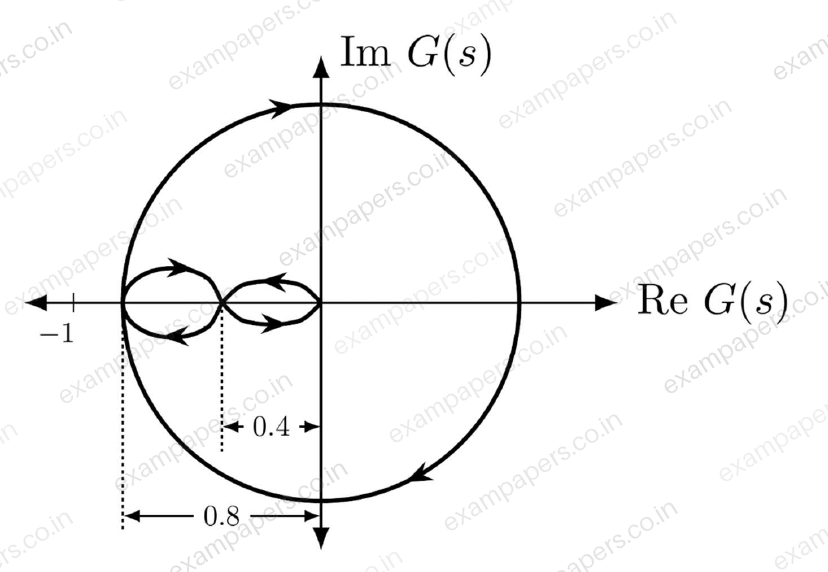
Your answerChoose one option.
Log in to check the answer
You can attempt this question now. Sign in to view the answer key, explanations and discussion.Log in to check answerQuestion 22
Open questionECMCQ1 markNeeds review
The root-locus plot of a closed-loop system with unity negative feedback and transfer function
in the forward path is shown in the figure. Note that
is varied from 0 to
.Select the transfer function
that results in the root-locus plot of the closed-loop system as shown in the figure. 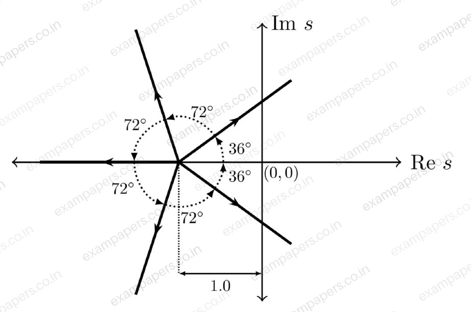
Your answerChoose one option.
Log in to check the answer
You can attempt this question now. Sign in to view the answer key, explanations and discussion.Log in to check answerQuestion 23
Open questionECMCQ1 markNeeds review
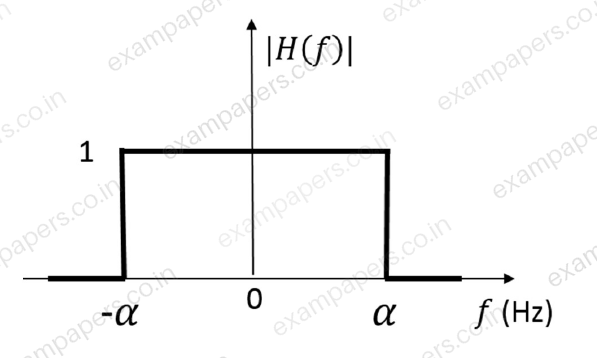
The frequency response
of a linear time-invariant system has magnitude as shown in the figure.Statement I: The system is necessarily a pure delay system for inputs which are bandlimited to
.Statement II: For any wide-sense stationary input process with power spectral density
, the output power spectral density
obeys
for
.Which one of the following combinations is true?
Your answerChoose one option.
Log in to check the answer
You can attempt this question now. Sign in to view the answer key, explanations and discussion.Log in to check answerQuestion 24
Open questionECMCQ1 markNeeds review
In a circuit, there is a series connection of an ideal resistor and an ideal capacitor. The conduction current (in Amperes) through the resistor is
. The displacement current (in Amperes) through the capacitor is ________.Your answerChoose one option.
Log in to check the answer
You can attempt this question now. Sign in to view the answer key, explanations and discussion.Log in to check answerQuestion 36
Open questionECMCQ2 marksNeeds review
The function
attains its minimum over the interval
at
________. (Here
is the natural logarithm of
.)Your answerChoose one option.
Log in to check the answer
You can attempt this question now. Sign in to view the answer key, explanations and discussion.Log in to check answer