
Electronics and Communication Engineering
GATE ECE Number representations PYQs
Build your understanding with focused practice from past exam papers.
How to practice Number representations
Attempt a question, record the concept and assumptions, then check the available answer. Rework mistakes after revising the relevant concepts. Topic tags can overlap; review the question context.
Questions 1–10 of 12. Imported answers require independent review unless marked reviewed.
Question 20
Open questionECMCQ1 markNeeds review
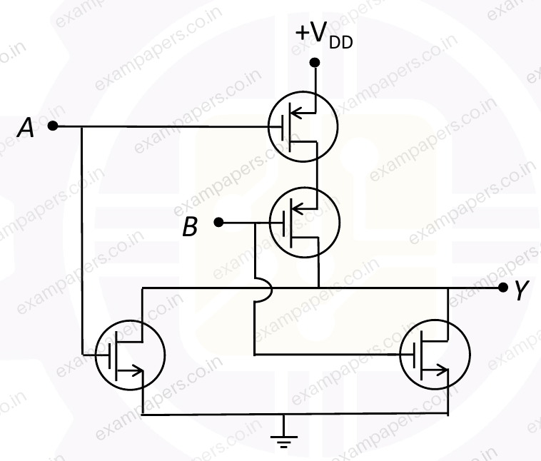
In the circuit shown in the Figure, A and B are logic inputs and Y is the logic output.
Which of the following logic operations is realized by the circuit?
Your answerChoose one option.
Log in to check the answer
You can attempt this question now. Sign in to view the answer key, explanations and discussion.Log in to check answerQuestion 45
Open questionECMCQ2 marksNeeds review
What is the 10’s complement of
?Your answerChoose one option.
Log in to check the answer
You can attempt this question now. Sign in to view the answer key, explanations and discussion.Log in to check answerQuestion 48
Open questionECMCQ2 marksNeeds review
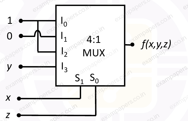
A Boolean function,
with
as MSB and
as LSB is realized by 4:1 multiplexer (MUX) with select lines,
and
(
is MSB,
is LSB) and inputs,
as shown in the Figure.Which of the following options is the correct expression of
? 
Your answerChoose one option.
Log in to check the answer
You can attempt this question now. Sign in to view the answer key, explanations and discussion.Log in to check answerQuestion 56
Open questionECMSQ2 marksNeeds review
Consider the four-variable Boolean function,
with ‘
’ as MSB and ‘
’ as LSB. Which of the following expressions is/are the valid form(s) of
?Your answerSelect all correct options. You can choose more than one.
Log in to check the answer
You can attempt this question now. Sign in to view the answer key, explanations and discussion.Log in to check answerQuestion 23
Open questionECMCQ1 markNeeds review
A 3-input majority logic gate has inputs
,
, and
. The output
of the gate is logic ‘1’ if two or more of the inputs are logic ‘1’. The output
is logic ‘0’ if two or more of the inputs are logic ‘0’. Which one of the following options is a Boolean expression of the output
?Your answerChoose one option.
Log in to check the answer
You can attempt this question now. Sign in to view the answer key, explanations and discussion.Log in to check answerQuestion 24
Open questionECMCQ1 markNeeds review
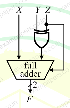
A full adder and an XOR gate are used to design a digital circuit with inputs X, Y, and Z, and output F, as shown below. The input Z is connected to the carry-in input of the full adder.
If the input Z is set to logic ‘1’, then the circuit functions as ______ with X and Y as inputs.
Your answerChoose one option.
Log in to check the answer
You can attempt this question now. Sign in to view the answer key, explanations and discussion.Log in to check answerQuestion 29
Open questionECNAT1 markNeeds review
In a number system of base
, the equation
has
as one of its solutions. The value of
is ______.Log in to check the answer
You can attempt this question now. Sign in to view the answer key, explanations and discussion.Log in to check answerQuestion 23
Open questionECMCQ1 markNeeds review
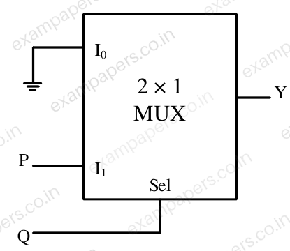
In the circuit shown below, P and Q are the inputs. The logical function realized by the circuit shown below is
Your answerChoose one option.
Log in to check the answer
You can attempt this question now. Sign in to view the answer key, explanations and discussion.Log in to check answerQuestion 11
Open questionECMCQ1 markNeeds review
If
, where
and
indicate the bases of the corresponding numbers, thenYour answerChoose one option.
Log in to check the answer
You can attempt this question now. Sign in to view the answer key, explanations and discussion.Log in to check answerQuestion 10
Open questionECMCQ1 markNeeds review
The figure below shows a multiplexer where
and
are the select lines,
to
are the input data lines, EN is the enable line, and
is the output.
is 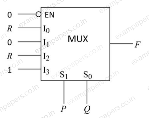
Your answerChoose one option.
Log in to check the answer
You can attempt this question now. Sign in to view the answer key, explanations and discussion.Log in to check answer