
Electronics and Communication Engineering
GATE ECE Op-amp circuits PYQs
Build your understanding with focused practice from past exam papers.
Questions 21–24 of 24. Imported answers require independent review unless marked reviewed.
Question 38
Open questionECNAT2 marksNeeds review
An op-amp based circuit is implemented as shown below.
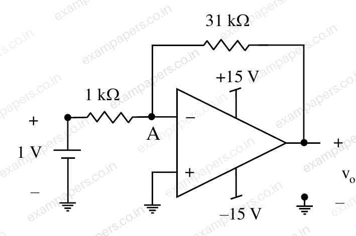
In the above circuit, assume the op-amp to be ideal. The voltage (in volts, correct to one decimal place) at node A, connected to the negative input of the op-amp as indicated in the figure is ______.
Log in to check the answer
You can attempt this question now. Sign in to view the answer key, explanations and discussion.Log in to check answerQuestion 12
Open questionECMCQ1 markNeeds review
For the operational amplifier circuit shown, the output saturation voltages are
. The upper and lower threshold voltages for the circuit are, respectively, 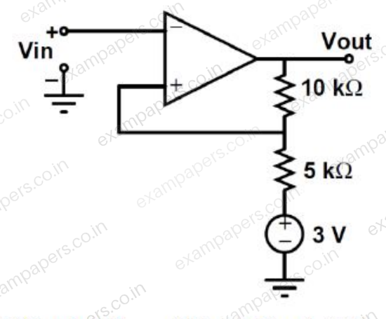
Your answerChoose one option.
Log in to check the answer
You can attempt this question now. Sign in to view the answer key, explanations and discussion.Log in to check answerQuestion 42
Open questionECNAT2 marksNeeds review
The amplifier circuit shown in the figure is implemented using a compensated operational amplifier (op-amp), and has an open-loop voltage gain,
and an open-loop cut-off frequency,
. The voltage gain of the amplifier at 15 kHz, in V/V, is ____________. 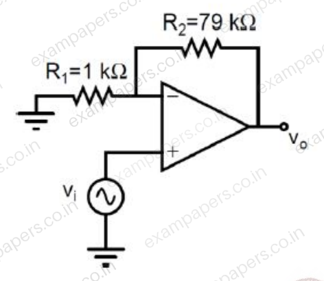
Log in to check the answer
You can attempt this question now. Sign in to view the answer key, explanations and discussion.Log in to check answerQuestion 42
Open questionECNAT2 marksNeeds review
In the voltage reference circuit shown in the figure, the op-amp is ideal and the transistors Q₁, Q₂, ..., Q₃ are identical in all respects and have infinitely large values of common-emitter current gain (β). The collector current (
) of the transistors is related to their base-emitter voltage (
) by the relation
, where
is the saturation current. Assume that the voltage
shown in the figure is 0.7 V and the thermal voltage
. 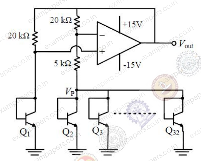
The output voltage
(in volts) is ______Log in to check the answer
You can attempt this question now. Sign in to view the answer key, explanations and discussion.Log in to check answer