
Electronics and Communication Engineering
GATE ECE topic:circuit-analysis PYQs
Build your understanding with focused practice from past exam papers.
Questions 31–40 of 50. Imported answers require independent review unless marked reviewed.
Question 47
Open questionECNAT2 marksNeeds review
The circuit in the figure contains a current source driving a load having an inductor and a resistor in series, with a shunt capacitor across the load. The ammeter is assumed to have zero resistance. The switch is closed at time
. 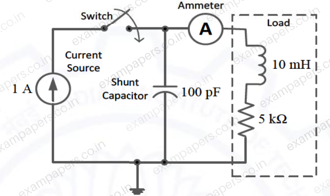
Initially, when the switch is open, the capacitor is discharged and the ammeter reads zero ampere. After the switch is closed, the ammeter reading keeps fluctuating for some time till it settles to a final steady value. The maximum ammeter reading that one will observe after the switch is closed (rounded off to two decimal places) is ______ A.
Log in to check the answer
You can attempt this question now. Sign in to view the answer key, explanations and discussion.Log in to check answerQuestion 9
Open questionECMCQ1 markNeeds review
In the circuit shown below, the Thevenin voltage
is 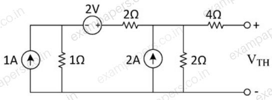
Your answerChoose one option.
Log in to check the answer
You can attempt this question now. Sign in to view the answer key, explanations and discussion.Log in to check answerQuestion 15
Open questionECNAT1 markNeeds review
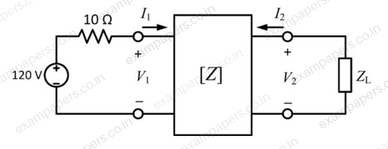
In the given circuit, the two-port network has the impedance matrix
The value of
for which maximum power is transferred to the load is ______
. 
Log in to check the answer
You can attempt this question now. Sign in to view the answer key, explanations and discussion.Log in to check answerQuestion 16
Open questionECNAT1 markNeeds review
The current in the RL-circuit shown below is
A. The value of the inductor (rounded off to two decimal places) is ______ H. 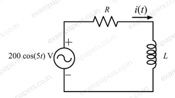
Log in to check the answer
You can attempt this question now. Sign in to view the answer key, explanations and discussion.Log in to check answerQuestion 28
Open questionECMCQ2 marksNeeds review
The current I in the given network is
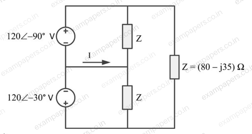
Your answerChoose one option.
Log in to check the answer
You can attempt this question now. Sign in to view the answer key, explanations and discussion.Log in to check answerQuestion 30
Open questionECMCQ2 marksNeeds review
For the given circuit, which one of the following is the correct state equation?
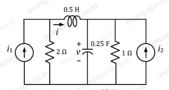
Your answerChoose one option.
Log in to check the answer
You can attempt this question now. Sign in to view the answer key, explanations and discussion.Log in to check answerQuestion 30
Open questionECMCQ2 marksNeeds review
In the circuit shown, if
volts,
and
, then the steady-state current
, in milliamperes (mA), is 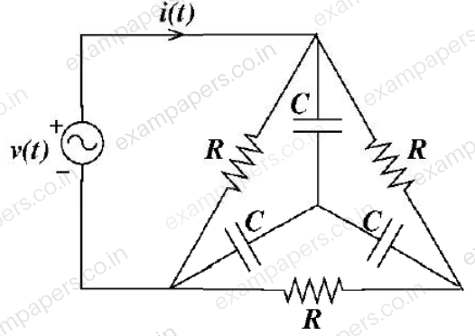
Your answerChoose one option.
Log in to check the answer
You can attempt this question now. Sign in to view the answer key, explanations and discussion.Log in to check answerQuestion 41
Open questionECNAT2 marksNeeds review
The RC circuit shown below has a variable resistance
given by the following expression:
where
, and
. We are also given that
and the source voltage is
. If the current at time
is 1 A, then the current
, in amperes, at time
is __________ (rounded off to 2 decimal places). 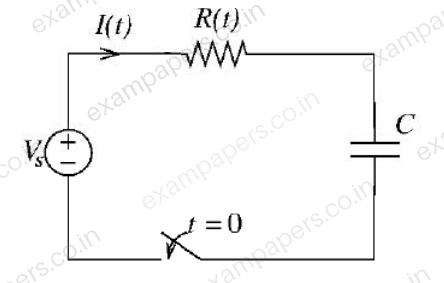
Log in to check the answer
You can attempt this question now. Sign in to view the answer key, explanations and discussion.Log in to check answerQuestion 52
Open questionECNAT2 marksNeeds review
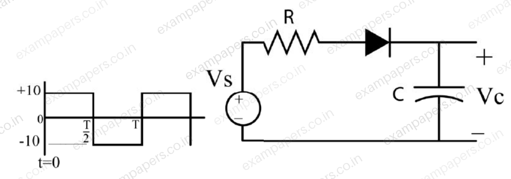
In the circuit shown,
is a 10 V square wave of period,
with
and
. The capacitor is initially uncharged at
, and the diode is assumed to be ideal. The voltage across the capacitor (
) at 3 ms is equal to ____ volts (rounded off to one decimal place).
Log in to check the answer
You can attempt this question now. Sign in to view the answer key, explanations and discussion.Log in to check answerQuestion 25
Open questionECNAT1 markNeeds review
The ABCD matrix for a two-port network is defined by:
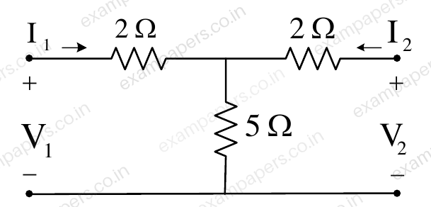
The parameter
for the given two-port network (in ohms, correct to two decimal places) is ________.Log in to check the answer
You can attempt this question now. Sign in to view the answer key, explanations and discussion.Log in to check answer