
Electronics and Communication Engineering
GATE ECE topic:circuit-analysis PYQs
Build your understanding with focused practice from past exam papers.
Questions 41–50 of 50. Imported answers require independent review unless marked reviewed.
Question 35
Open questionECMCQ2 marksNeeds review
For the circuit given in the figure, the voltage
(in volts) across the capacitor is 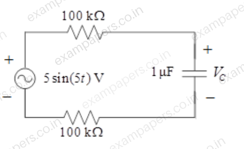
Your answerChoose one option.
Log in to check the answer
You can attempt this question now. Sign in to view the answer key, explanations and discussion.Log in to check answerQuestion 36
Open questionECNAT2 marksNeeds review
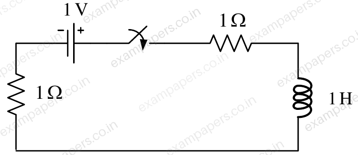
For the circuit given in the figure, the magnitude of the loop current (in amperes, correct to three decimal places) 0.5 second after closing the switch is ______.
Log in to check the answer
You can attempt this question now. Sign in to view the answer key, explanations and discussion.Log in to check answerQuestion 53
Open questionECNAT2 marksNeeds review
Consider the network shown below with
,
and
. The network is connected to a constant voltage source of 11 V. 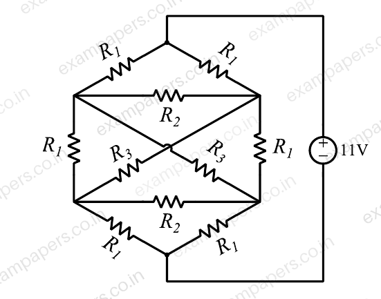
The magnitude of the current (in amperes, accurate to two decimal places) through the source is ______.
Log in to check the answer
You can attempt this question now. Sign in to view the answer key, explanations and discussion.Log in to check answerQuestion 5
Open questionECNAT1 markNeeds review
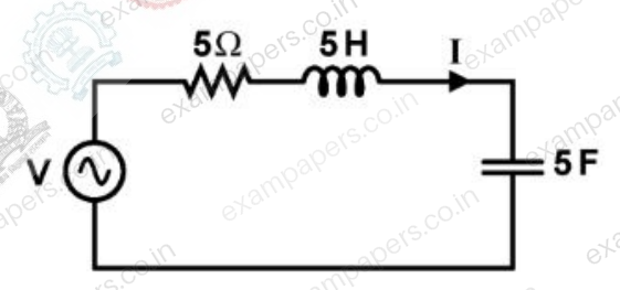
In the circuit shown, V is a sinusoidal voltage source. The current I is in phase with voltage V. The ratio
is _________.
Log in to check the answer
You can attempt this question now. Sign in to view the answer key, explanations and discussion.Log in to check answerQuestion 6
Open questionECNAT1 markNeeds review
A connection is made consisting of resistance A in series with a parallel combination of resistances B and C. Three resistors of value 10 Ω, 5 Ω, 2 Ω are provided. Consider all possible permutations of the given resistors into the positions A, B, C, and identify the configurations with maximum possible overall resistance, and also the ones with minimum possible overall resistance. The ratio of maximum to minimum values of the resistances (up to second decimal place) is __________.
Log in to check the answer
You can attempt this question now. Sign in to view the answer key, explanations and discussion.Log in to check answerQuestion 7
Open questionECNAT1 markNeeds review
In the circuit shown, the positive angular frequency
(in radians per second) at which the magnitude of the phase difference between the voltages
and
equals
radians, is ______.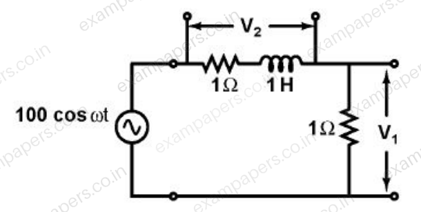
Log in to check the answer
You can attempt this question now. Sign in to view the answer key, explanations and discussion.Log in to check answerQuestion 31
Open questionECNAT2 marksNeeds review
The switch in the circuit, shown in the figure, was open for a long time and is closed at
. 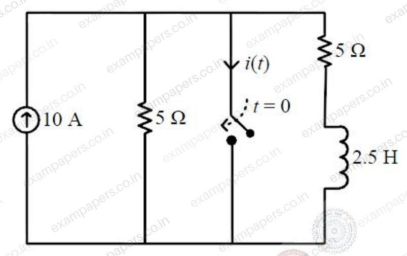
The current
(in ampere) at
seconds is ________.Log in to check the answer
You can attempt this question now. Sign in to view the answer key, explanations and discussion.Log in to check answerQuestion 32
Open questionECNAT2 marksNeeds review
Consider the circuit shown in the figure.
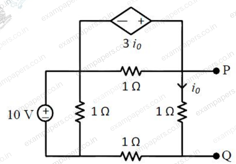
The Thevenin equivalent resistance (in
) across P-Q is ________.Log in to check the answer
You can attempt this question now. Sign in to view the answer key, explanations and discussion.Log in to check answerQuestion 34
Open questionECNAT2 marksNeeds review
The figure shows an RLC circuit excited by the sinusoidal voltage
Volts, where
is in seconds. The ratio
is __________.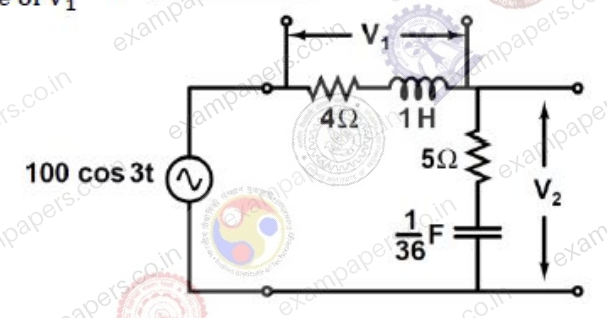
Log in to check the answer
You can attempt this question now. Sign in to view the answer key, explanations and discussion.Log in to check answerQuestion 35
Open questionECNAT2 marksNeeds review
In the circuit shown, the voltage
is described by:
where
is in seconds. The time (in seconds) at which the current
in the circuit will reach the value 2 Amperes is __________.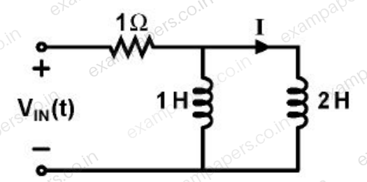
Log in to check the answer
You can attempt this question now. Sign in to view the answer key, explanations and discussion.Log in to check answer