
Electronics and Communication Engineering
GATE ECE topic:communication-engineering PYQs
Build your understanding with focused practice from past exam papers.
Questions 81–90 of 715. Imported answers require independent review unless marked reviewed.
Question 16
Open questionECMCQ1 markNeeds review
The Nyquist plot of a system is given in the figure below. Let
,
,
, and
be the positive frequencies at the points
,
,
, and
, respectively. Which one of the following statements is TRUE? 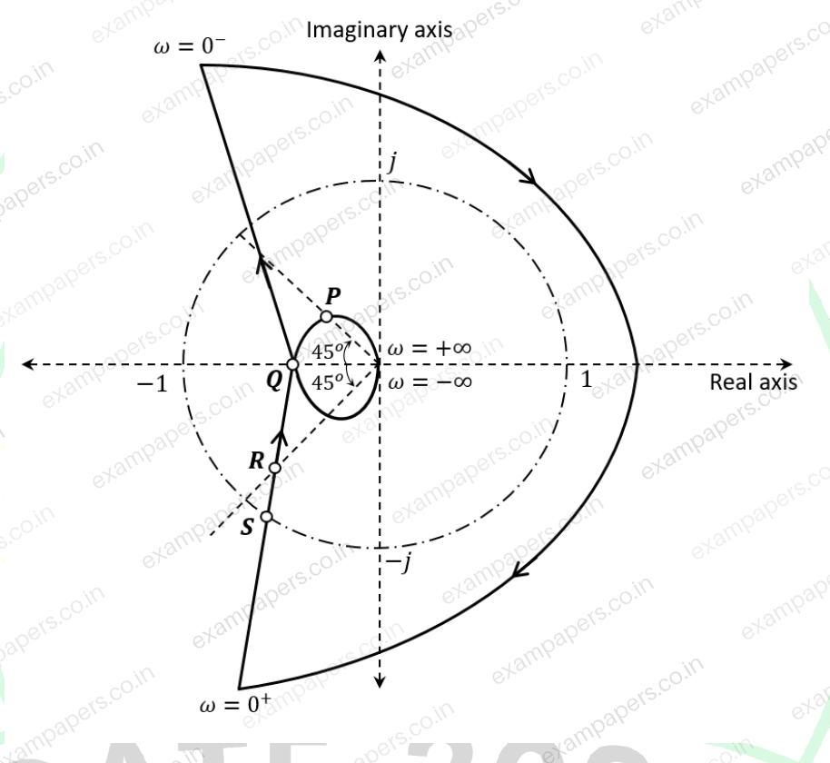
Your answerChoose one option.
Log in to check the answer
You can attempt this question now. Sign in to view the answer key, explanations and discussion.Log in to check answerQuestion 17
Open questionECMCQ1 markNeeds review
Consider the discrete-time system below with input
and output
. In the figure,
and
denote the impulse responses of LTI Subsystems 1 and 2, respectively. Also,
is the unit impulse, and
. Assuming
, the overall system (denoted by the dashed box) is _____. 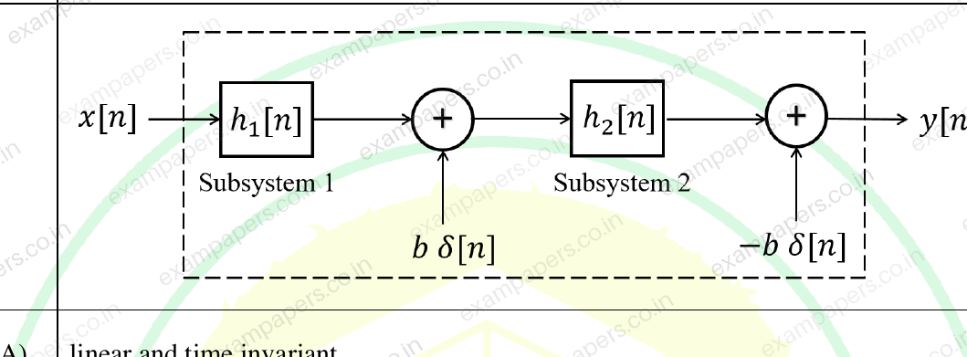
Your answerChoose one option.
Log in to check the answer
You can attempt this question now. Sign in to view the answer key, explanations and discussion.Log in to check answerQuestion 18
Open questionECMCQ1 markNeeds review
Consider a continuous-time, real-valued signal
whose Fourier transform
exists. Which one of the following statements is always TRUE?Your answerChoose one option.
Log in to check the answer
You can attempt this question now. Sign in to view the answer key, explanations and discussion.Log in to check answerQuestion 19
Open questionECMCQ1 markNeeds review
Consider a part of an electrical network as shown below. Some node voltages, and the current flowing through the
resistor are as indicated. The voltage (in Volts) at node
is _____. 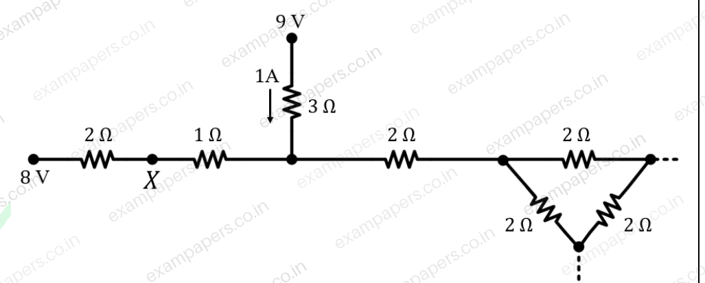
Your answerChoose one option.
Log in to check the answer
You can attempt this question now. Sign in to view the answer key, explanations and discussion.Log in to check answerQuestion 20
Open questionECMCQ1 markNeeds review
Let
,
, and
be the currents flowing through the capacitor, inductor, and resistor, respectively, in the circuit given below. The AC admittances are given in Siemens (S). Which one of the following is TRUE? 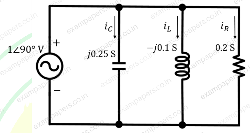
Your answerChoose one option.
Log in to check the answer
You can attempt this question now. Sign in to view the answer key, explanations and discussion.Log in to check answerQuestion 21
Open questionECMCQ1 markNeeds review
A simplified small-signal equivalent circuit of a BJT-based amplifier is given below. The small-signal voltage gain
(in V/V) is ________. 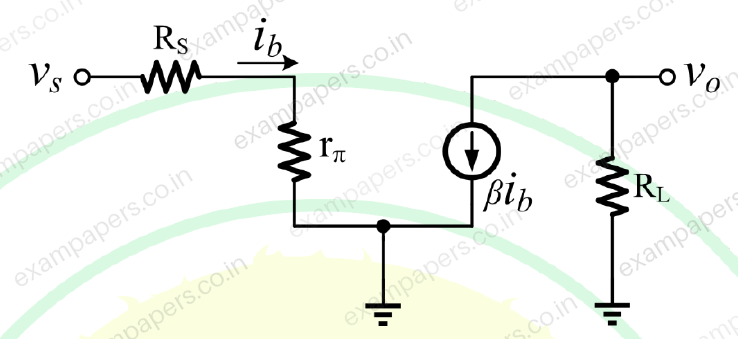
Your answerChoose one option.
Log in to check the answer
You can attempt this question now. Sign in to view the answer key, explanations and discussion.Log in to check answerQuestion 22
Open questionECMCQ1 markNeeds review
The ideal BJT in the circuit given below is biased in the active region with a
of 100. If
is 10
A, then
(in Volts, rounded off to two decimal places) is ______ . 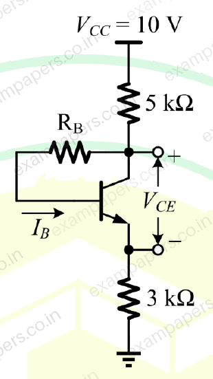
Your answerChoose one option.
Log in to check the answer
You can attempt this question now. Sign in to view the answer key, explanations and discussion.Log in to check answerQuestion 23
Open questionECMCQ1 markNeeds review
A 3-input majority logic gate has inputs
,
, and
. The output
of the gate is logic ‘1’ if two or more of the inputs are logic ‘1’. The output
is logic ‘0’ if two or more of the inputs are logic ‘0’. Which one of the following options is a Boolean expression of the output
?Your answerChoose one option.
Log in to check the answer
You can attempt this question now. Sign in to view the answer key, explanations and discussion.Log in to check answerQuestion 24
Open questionECMCQ1 markNeeds review
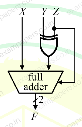
A full adder and an XOR gate are used to design a digital circuit with inputs X, Y, and Z, and output F, as shown below. The input Z is connected to the carry-in input of the full adder.
If the input Z is set to logic ‘1’, then the circuit functions as ______ with X and Y as inputs.
Your answerChoose one option.
Log in to check the answer
You can attempt this question now. Sign in to view the answer key, explanations and discussion.Log in to check answerQuestion 25
Open questionECMSQ1 markNeeds review
Consider the function
, defined as
Which of the following statements is/are correct?
(Here,
is the set of real numbers.)Your answerSelect all correct options. You can choose more than one.
Log in to check the answer
You can attempt this question now. Sign in to view the answer key, explanations and discussion.Log in to check answer