
Electronics and Communication Engineering
GATE ECE topic:control-systems PYQs
Build your understanding with focused practice from past exam papers.
Questions 21–30 of 56. Imported answers require independent review unless marked reviewed.
Question 21
Open questionECMCQ1 markNeeds review
Consider a closed-loop control system with unity negative feedback and
in the forward path, where the gain
. The complete Nyquist plot of the transfer function
is shown in the figure. Note that the Nyquist contour has been chosen to have the clockwise sense. Assume
has no poles on the closed right-half of the complex plane. The number of poles of the closed-loop transfer function in the closed right-half of the complex plane is ____________. 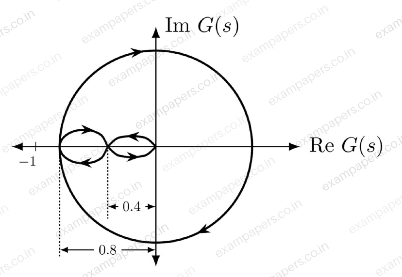
Your answerChoose one option.
Log in to check the answer
You can attempt this question now. Sign in to view the answer key, explanations and discussion.Log in to check answerQuestion 22
Open questionECMCQ1 markNeeds review
The root-locus plot of a closed-loop system with unity negative feedback and transfer function
in the forward path is shown in the figure. Note that
is varied from 0 to
.Select the transfer function
that results in the root-locus plot of the closed-loop system as shown in the figure. 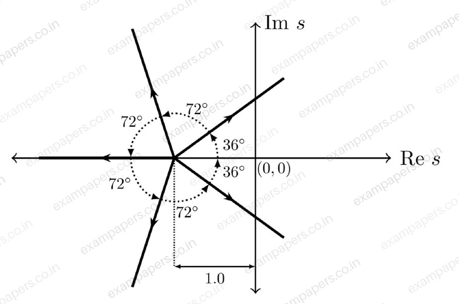
Your answerChoose one option.
Log in to check the answer
You can attempt this question now. Sign in to view the answer key, explanations and discussion.Log in to check answerQuestion 44
Open questionECMCQ2 marksNeeds review
Consider an even polynomial
given by
where
is an unknown real parameter. The complete range of
for which
has all its roots on the imaginary axis is ________.Your answerChoose one option.
Log in to check the answer
You can attempt this question now. Sign in to view the answer key, explanations and discussion.Log in to check answerQuestion 50
Open questionECMSQ2 marksNeeds review
Two linear time-invariant systems with transfer functions
and
have unit step responses
and
, respectively. Which of the following statements is/are true?Your answerSelect all correct options. You can choose more than one.
Log in to check the answer
You can attempt this question now. Sign in to view the answer key, explanations and discussion.Log in to check answerQuestion 60
Open questionECNAT2 marksNeeds review
The block diagram of a closed-loop control system is shown in the figure.
,
, and
are the Laplace transforms of the time-domain signals
,
, and
, respectively. Let the error signal be defined as
. Assuming the reference input
for all
, the steady-state error
, due to a unit step disturbance
, is ________ (rounded off to two decimal places). 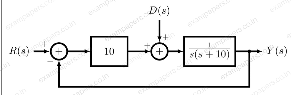
Log in to check the answer
You can attempt this question now. Sign in to view the answer key, explanations and discussion.Log in to check answerQuestion 13
Open questionECMCQ1 markNeeds review
The block diagram of a feedback control system is shown in the figure. The transfer function
of the system is 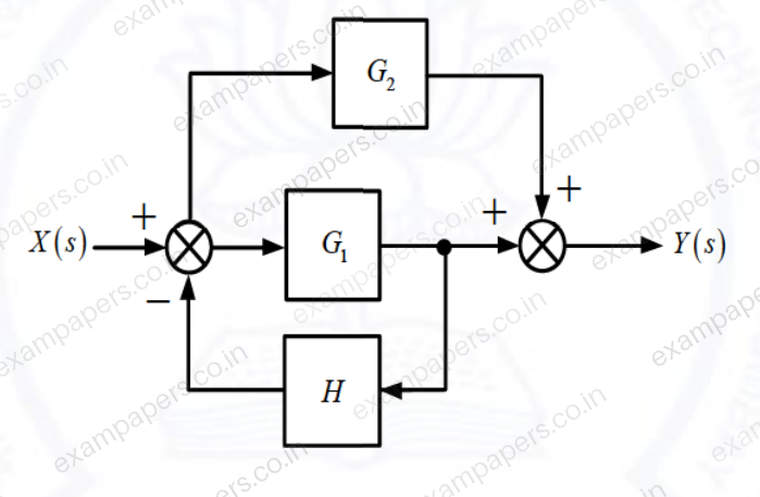
Your answerChoose one option.
Log in to check the answer
You can attempt this question now. Sign in to view the answer key, explanations and discussion.Log in to check answerQuestion 14
Open questionECMCQ1 markNeeds review
The complete Nyquist plot of the open-loop transfer function
of a feedback control system is shown in the figure. If
has one zero in the right-half of the
-plane, the number of poles that the closed-loop system will have in the right-half of the
-plane is 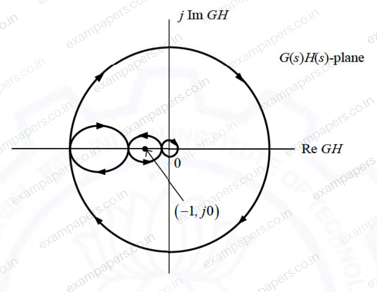
Your answerChoose one option.
Log in to check the answer
You can attempt this question now. Sign in to view the answer key, explanations and discussion.Log in to check answerQuestion 33
Open questionECMCQ2 marksNeeds review
The electrical system shown in the figure converts input source current
to output voltage
. 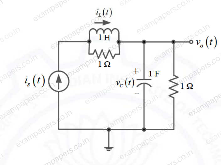
Current
in the inductor and voltage
across the capacitor are taken as the state variables, both assumed to be initially equal to zero, i.e.,
and
. The system isYour answerChoose one option.
Log in to check the answer
You can attempt this question now. Sign in to view the answer key, explanations and discussion.Log in to check answerQuestion 48
Open questionECNAT2 marksNeeds review
A unity feedback system that uses proportional-integral (PI) control is shown in the figure.
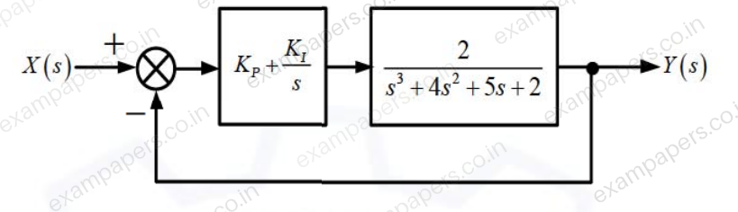
The stability of the overall system is controlled by tuning the PI control parameters
and
. The maximum value of
that can be chosen so as to keep the overall system stable or, in the worst case, marginally stable (rounded off to three decimal places) is _____.Log in to check the answer
You can attempt this question now. Sign in to view the answer key, explanations and discussion.Log in to check answerQuestion 11
Open questionECMCQ1 markNeeds review
The pole-zero map of a rational function
is shown below. When the closed contour
is mapped into the
-plane, then the mapping encircles 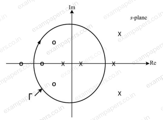
Your answerChoose one option.
Log in to check the answer
You can attempt this question now. Sign in to view the answer key, explanations and discussion.Log in to check answer