
Electronics and Communication Engineering
GATE ECE topic:op-amp-circuits PYQs
Build your understanding with focused practice from past exam papers.
How to practice topic:op-amp-circuits
Attempt a question, record the concept and assumptions, then check the available answer. Rework mistakes after revising the relevant concepts. Topic tags can overlap; review the question context.
Questions 1–10 of 24. Imported answers require independent review unless marked reviewed.
Question 17
Open questionECMCQ1 markNeeds review
The ideal OP-AMP circuit shown in the Figure produces output voltage
when the Switch, S, is open.Which of the options represents the output voltage when S is closed?
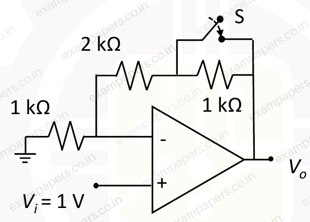
Your answerChoose one option.
Log in to check the answer
You can attempt this question now. Sign in to view the answer key, explanations and discussion.Log in to check answerQuestion 53
Open questionECMCQ2 marksNeeds review
A circuit using an ideal OP-AMP is shown in the Figure.
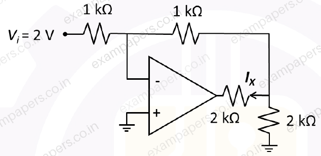
Which of the following options gives the correct value of the current
?Your answerChoose one option.
Log in to check the answer
You can attempt this question now. Sign in to view the answer key, explanations and discussion.Log in to check answerQuestion 62
Open questionECNAT2 marksNeeds review
Consider an ideal OP-AMP circuit as shown in the Figure. The resistances
. The magnitude of the closed loop gain is ___. (rounded off to two decimal places) 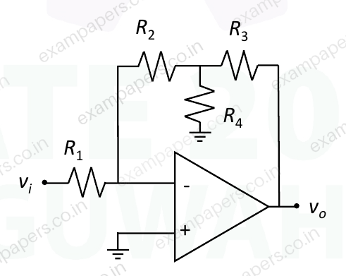
Log in to check the answer
You can attempt this question now. Sign in to view the answer key, explanations and discussion.Log in to check answerQuestion 29
Open questionECMSQ1 markNeeds review
Which of the following statements is/are TRUE with respect to an ideal opamp?
Your answerSelect all correct options. You can choose more than one.
Log in to check the answer
You can attempt this question now. Sign in to view the answer key, explanations and discussion.Log in to check answerQuestion 34
Open questionECNAT1 markNeeds review
All the components in the bandpass filter given below are ideal. The lower
frequency of the filter is 1 MHz.The upper
frequency (in MHz, rounded off to the nearest integer) is ________. 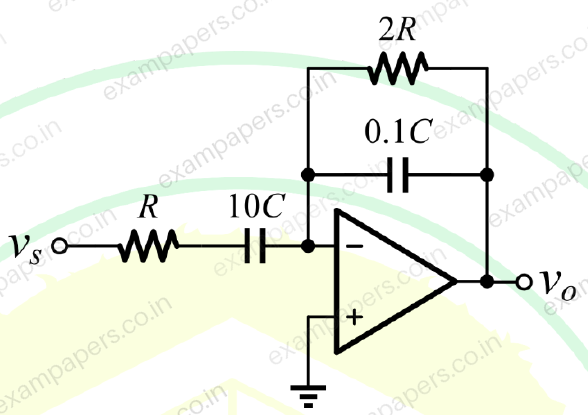
Log in to check the answer
You can attempt this question now. Sign in to view the answer key, explanations and discussion.Log in to check answerQuestion 49
Open questionECMCQ2 marksNeeds review
The opamps in the circuit shown are ideal, but have saturation voltages of ±10 V.
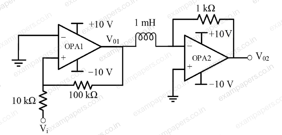
Assume that the initial inductor current is 0 A. The input voltage (
) is a triangular signal with peak voltages of ±2 V and time period of 8 μs. Which one of the following statements is true?Your answerChoose one option.
Log in to check the answer
You can attempt this question now. Sign in to view the answer key, explanations and discussion.Log in to check answerQuestion 50
Open questionECMCQ2 marksNeeds review
In the circuit below, the opamp is ideal.
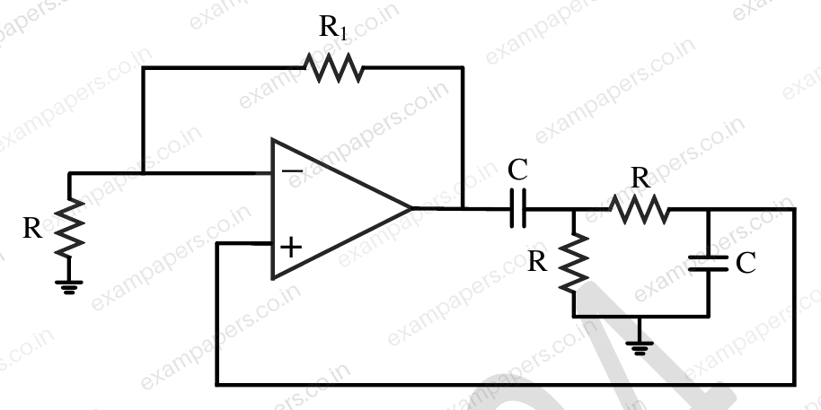
[Circuit diagram: an ideal op-amp relaxation oscillator with resistors R, R₁ and R, capacitors C and C, and ground connections.] If the circuit is to show sustained oscillations, the respective values of
and the corresponding frequency of oscillation are ______.Your answerChoose one option.
Log in to check the answer
You can attempt this question now. Sign in to view the answer key, explanations and discussion.Log in to check answerQuestion 39
Open questionECMCQ2 marksNeeds review
The
of the circuit shown below is 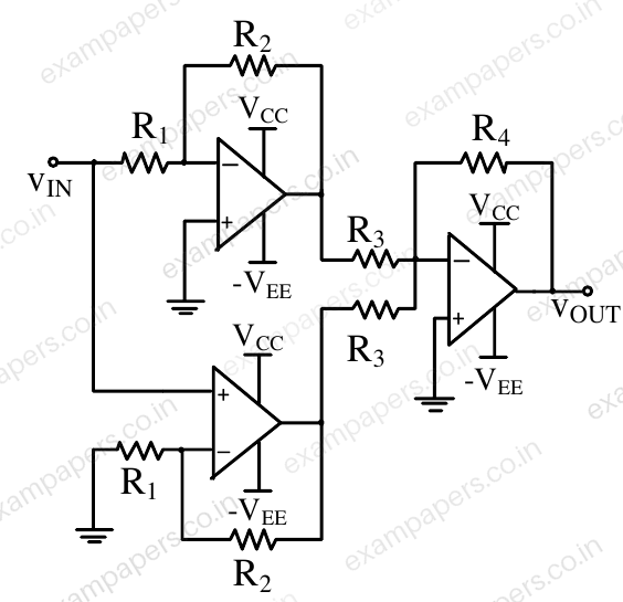
Your answerChoose one option.
Log in to check the answer
You can attempt this question now. Sign in to view the answer key, explanations and discussion.Log in to check answerQuestion 26
Open questionECMSQ1 markNeeds review
An ideal OPAMP circuit with a sinusoidal input is shown in the figure. The 3 dB frequency is the frequency at which the magnitude of the voltage gain decreases by 3 dB from the maximum value. Which of the options is/are correct?
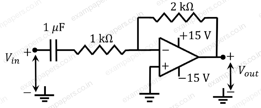
Your answerSelect all correct options. You can choose more than one.
Log in to check the answer
You can attempt this question now. Sign in to view the answer key, explanations and discussion.Log in to check answerQuestion 41
Open questionECMCQ2 marksNeeds review
For the following circuit with an ideal OPAMP, the difference between the maximum and the minimum values of the capacitor voltage (
) is ________. 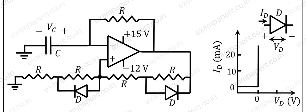
Your answerChoose one option.
Log in to check the answer
You can attempt this question now. Sign in to view the answer key, explanations and discussion.Log in to check answer