
Electronics and Communication Engineering
GATE ECE topic:op-amp-circuits PYQs
Build your understanding with focused practice from past exam papers.
Questions 11–20 of 24. Imported answers require independent review unless marked reviewed.
Question 42
Open questionECMCQ2 marksNeeds review
A circuit with an ideal OPAMP is shown. The Bode plot for the magnitude (in dB) of the gain transfer function (
) of the circuit is also provided (here,
is the angular frequency in rad/s). The values of
and
are ____________. 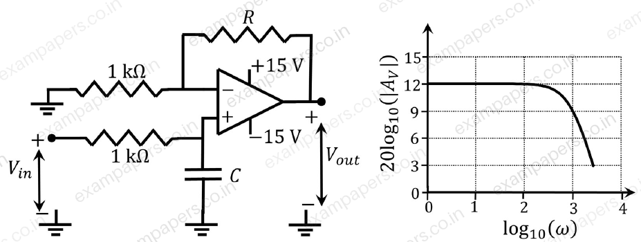
Your answerChoose one option.
Log in to check the answer
You can attempt this question now. Sign in to view the answer key, explanations and discussion.Log in to check answerQuestion 58
Open questionECNAT2 marksNeeds review
Consider the circuit shown with an ideal OPAMP. The output voltage
is ________ V (rounded off to two decimal places). 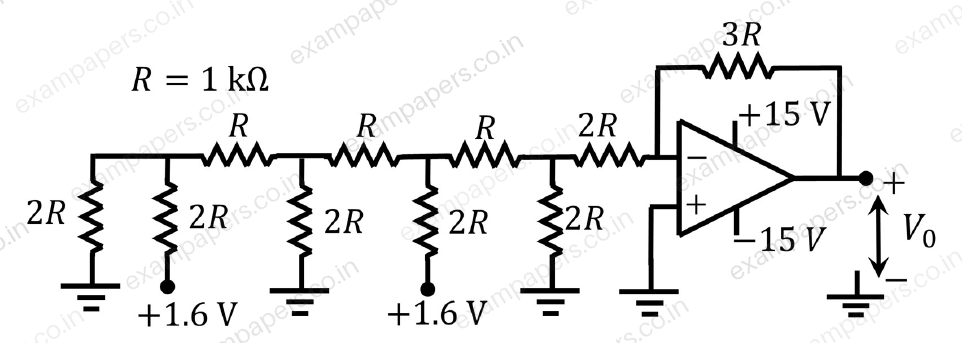
Log in to check the answer
You can attempt this question now. Sign in to view the answer key, explanations and discussion.Log in to check answerQuestion 9
Open questionECMCQ1 markNeeds review
For the circuit with an ideal OPAMP shown in the figure,
is fixed. 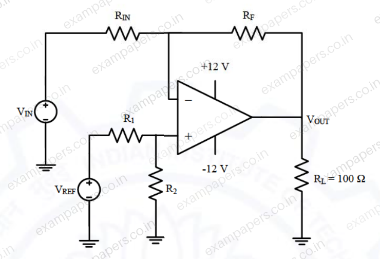
If
volt for
volt and
volt for
volt, where
is measured across
connected at the output of this OPAMP, the value of
isYour answerChoose one option.
Log in to check the answer
You can attempt this question now. Sign in to view the answer key, explanations and discussion.Log in to check answerQuestion 10
Open questionECMCQ1 markNeeds review
Consider the circuit with an ideal OPAMP shown in the figure. Assuming
and
, the condition at which
equals to zero is 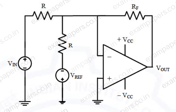
Your answerChoose one option.
Log in to check the answer
You can attempt this question now. Sign in to view the answer key, explanations and discussion.Log in to check answerQuestion 45
Open questionECNAT2 marksNeeds review
A circuit with an ideal OPAMP is shown in the figure. A pulse
of 20 ms duration is applied to the input. The capacitors are initially uncharged. 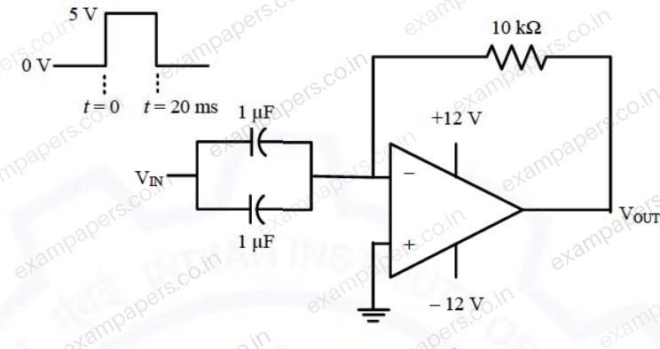
The output voltage
of this circuit at
(in integer) is ______ V.Log in to check the answer
You can attempt this question now. Sign in to view the answer key, explanations and discussion.Log in to check answerQuestion 8
Open questionECMCQ1 markNeeds review
The components in the circuit shown below are ideal. If the op-amp is in positive feedback and the input voltage
is a sine wave of amplitude 1 V, the output voltage
is 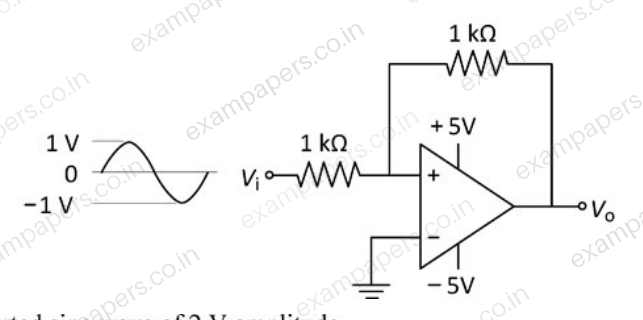
Your answerChoose one option.
Log in to check the answer
You can attempt this question now. Sign in to view the answer key, explanations and discussion.Log in to check answerQuestion 18
Open questionECNAT1 markNeeds review
In the circuit shown below, all the components are ideal. If
is +2 V, the current
sourced by the op-amp is ______ mA. 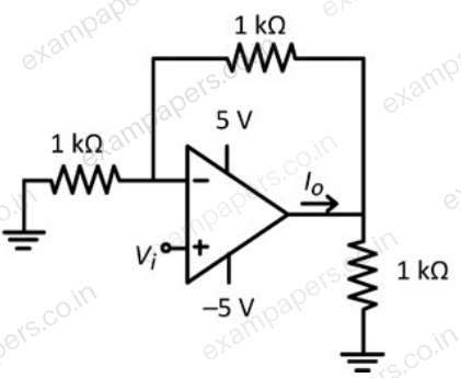
Log in to check the answer
You can attempt this question now. Sign in to view the answer key, explanations and discussion.Log in to check answerQuestion 41
Open questionECMCQ2 marksNeeds review
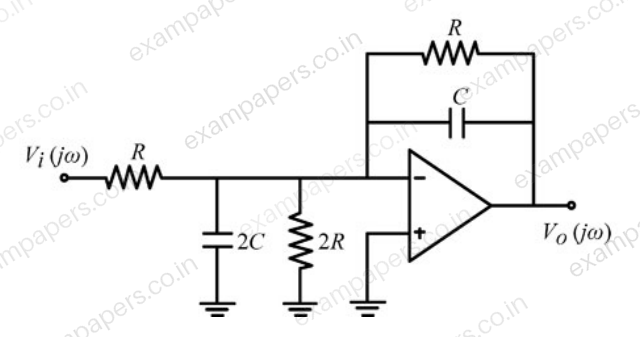
The components in the circuit given below are ideal. If R = 2 kΩ and C = 1 μF, the −3 dB cut-off frequency of the circuit in Hz is
Your answerChoose one option.
Log in to check the answer
You can attempt this question now. Sign in to view the answer key, explanations and discussion.Log in to check answerQuestion 2
Open questionECMCQ1 markNeeds review
In the circuit shown below, the op-amp is ideal and Zener voltage of the diode is 2.5 volts. At the input, unit step voltage is applied, i.e.
volts. Also, at t = 0, the voltage across each of the capacitors is zero.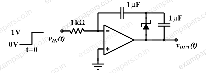
The time t, in milliseconds, at which the output voltage v_OUT crosses −10 V is
Your answerChoose one option.
Log in to check the answer
You can attempt this question now. Sign in to view the answer key, explanations and discussion.Log in to check answerQuestion 3
Open questionECMCQ1 markNeeds review
A good transimpedance amplifier has
Your answerChoose one option.
Log in to check the answer
You can attempt this question now. Sign in to view the answer key, explanations and discussion.Log in to check answer