
Electronics and Communication Engineering
GATE ECE topic:transmission-lines PYQs
Build your understanding with focused practice from past exam papers.
Questions 11–20 of 22. Imported answers require independent review unless marked reviewed.
Question 25
Open questionECNAT1 markNeeds review
The refractive indices of the core and cladding of an optical fiber are 1.50 and 1.48, respectively. The critical propagation angle, which is defined as the maximum angle that the light beam makes with the axis of the optical fiber to achieve the total internal reflection, (rounded off to two decimal places) is ______ degree.
Log in to check the answer
You can attempt this question now. Sign in to view the answer key, explanations and discussion.Log in to check answerQuestion 35
Open questionECMCQ2 marksNeeds review
The impedance matching network shown in the figure is to match a lossless line having characteristic impedance
with a load impedance
. A quarter-wave line having a characteristic impedance
is connected to
. Two stubs having characteristic impedance of 75 Ω each are connected to this quarter-wave line. One is a short-circuited (S.C.) stub of length
connected across PQ and the other is an open-circuited (O.C.) stub of length
connected across RS. 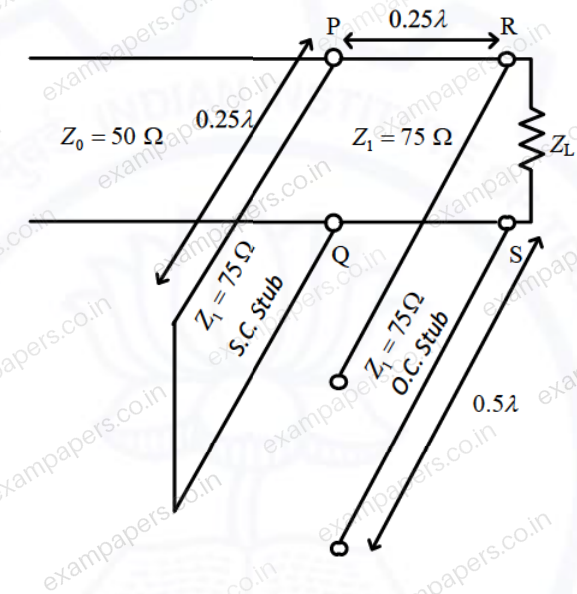
The impedance matching is achieved when the real part of
isYour answerChoose one option.
Log in to check the answer
You can attempt this question now. Sign in to view the answer key, explanations and discussion.Log in to check answerQuestion 54
Open questionECNAT2 marksNeeds review
A standard air-filled rectangular waveguide with dimensions
cm,
cm, operates at 3.4 GHz. For the dominant mode of wave propagation, the phase velocity of the signal is
. The value (rounded off to two decimal places) of
, where
denotes the velocity of light, is _____.Log in to check the answer
You can attempt this question now. Sign in to view the answer key, explanations and discussion.Log in to check answerQuestion 55
Open questionECNAT2 marksNeeds review
An antenna with a directive gain of 6 dB is radiating a total power of 16 kW. The amplitude of the electric field in free space at a distance of 8 km from the antenna in the direction of 6 dB gain (rounded off to three decimal places) is ______ V/m.
Log in to check the answer
You can attempt this question now. Sign in to view the answer key, explanations and discussion.Log in to check answerQuestion 13
Open questionECMCQ1 markNeeds review
The impedances
, for all
in the range
, map to the Smith chart asYour answerChoose one option.
Log in to check the answer
You can attempt this question now. Sign in to view the answer key, explanations and discussion.Log in to check answerQuestion 21
Open questionECNAT1 markNeeds review
A transmission line of length
and having a characteristic impedance of 50
is terminated with a load of 400
. The impedance (rounded off to two decimal places) seen at the input end of the transmission line is ______
.Log in to check the answer
You can attempt this question now. Sign in to view the answer key, explanations and discussion.Log in to check answerQuestion 43
Open questionECMCQ2 marksNeeds review
For an infinitesimally small dipole in free space, the electric field
in the far field is proportional to
, where
. A vertical infinitesimally small electric dipole (
) is placed at a distance
(
) above an infinite ideal conducting plane, as shown in the figure. The minimum value of
, for which one of the maxima in the far field radiation pattern occurs at
, is 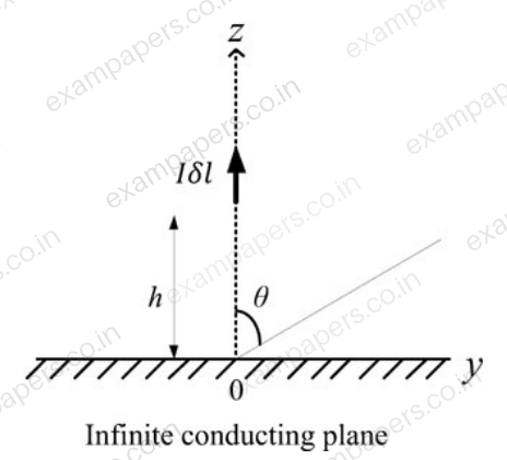
Your answerChoose one option.
Log in to check the answer
You can attempt this question now. Sign in to view the answer key, explanations and discussion.Log in to check answerQuestion 46
Open questionECNAT2 marksNeeds review
For a 2-port network consisting of an ideal lossless transformer, the parameter s₂₁ (rounded off to two decimal places) for a reference impedance of 10 Ω, is ______.
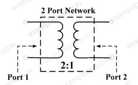
Log in to check the answer
You can attempt this question now. Sign in to view the answer key, explanations and discussion.Log in to check answerQuestion 10
Open questionECMCQ1 markNeeds review
The points P, Q, and R shown on the Smith chart (normalized impedance chart) in the following figure represent:
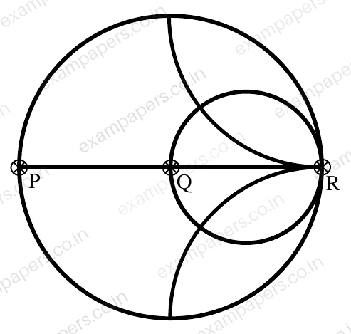
Your answerChoose one option.
Log in to check the answer
You can attempt this question now. Sign in to view the answer key, explanations and discussion.Log in to check answerQuestion 21
Open questionECNAT1 markNeeds review
A lossless transmission line has resistance per unit length
. The line is distortionless and has characteristic impedance of
. The attenuation constant (in Np/m, correct to three decimal places) of the line is ________.Log in to check the answer
You can attempt this question now. Sign in to view the answer key, explanations and discussion.Log in to check answer