
Electronics and Communication Engineering
GATE ECE year:2019 PYQs
Build your understanding with focused practice from past exam papers.
Questions 41–50 of 65. Imported answers require independent review unless marked reviewed.
Question 31
Open questionECMCQ2 marksNeeds review
Consider a causal second-order system with the transfer function
with a unit-step
as an input. Let
be the corresponding output. The time taken by the system output
to reach 94% of its steady-state value
, rounded off to two decimal places, isYour answerChoose one option.
Log in to check the answer
You can attempt this question now. Sign in to view the answer key, explanations and discussion.Log in to check answerQuestion 32
Open questionECMCQ2 marksNeeds review
The block diagram of a system is illustrated in the figure shown, where
is the input and
is the output. The transfer function
is 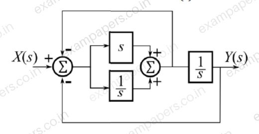
Your answerChoose one option.
Log in to check the answer
You can attempt this question now. Sign in to view the answer key, explanations and discussion.Log in to check answerQuestion 33
Open questionECMCQ2 marksNeeds review
Let the state-space representation of an LTI system be
where
are matrices,
is a scalar,
is the input to the system, and
is its output. Let
and
. Which one of the following options for
and
will ensure that the transfer function of this LTI system is
?Your answerChoose one option.
Log in to check the answer
You can attempt this question now. Sign in to view the answer key, explanations and discussion.Log in to check answerQuestion 34
Open questionECMCQ2 marksNeeds review
A single bit, equally likely to be 0 and 1, is to be sent across an additive white Gaussian noise (AWGN) channel with power spectral density
. Binary signaling, with
and
, is used for the transmission, along with an optimal receiver that minimizes the bit-error probability.
Let
form an orthonormal signal set.
If we choose
and
, we would obtain a certain bit-error probability
.
If we keep
, but take
, for what value of
would we obtain the same bit-error probability
?Your answerChoose one option.
Log in to check the answer
You can attempt this question now. Sign in to view the answer key, explanations and discussion.Log in to check answerQuestion 35
Open questionECMCQ2 marksNeeds review
The quantum efficiency (
) and responsivity (
) at a wavelength
(in
) in a p-i-n photodetector are related byYour answerChoose one option.
Log in to check the answer
You can attempt this question now. Sign in to view the answer key, explanations and discussion.Log in to check answerQuestion 36
Open questionECMCQ2 marksNeeds review
Two identical copper wires W1 and W2, placed in parallel as shown in the figure, carry currents
and
, respectively, in opposite directions. If the two wires are separated by a distance of
, then the magnitude of the magnetic field
between the wires at a distance
from W1 is 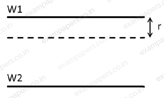
Your answerChoose one option.
Log in to check the answer
You can attempt this question now. Sign in to view the answer key, explanations and discussion.Log in to check answerQuestion 37
Open questionECMCQ2 marksNeeds review
The dispersion equation of a waveguide, which relates the wavenumber
to the frequency
, is
where the speed of light
m/s, and
is a constant. If the group velocity is
m/s, then the phase velocity isYour answerChoose one option.
Log in to check the answer
You can attempt this question now. Sign in to view the answer key, explanations and discussion.Log in to check answerQuestion 38
Open questionECMCQ2 marksNeeds review
In the circuit shown, the breakdown voltage and the maximum current of the Zener diode are 20 V and 60 mA, respectively. The values of
and
are 200
and 1 k
, respectively. What is the range of
that will maintain the Zener diode in the ‘on’ state? 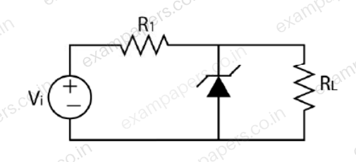
Your answerChoose one option.
Log in to check the answer
You can attempt this question now. Sign in to view the answer key, explanations and discussion.Log in to check answerQuestion 39
Open questionECMCQ2 marksNeeds review
The state transition diagram for the circuit shown is
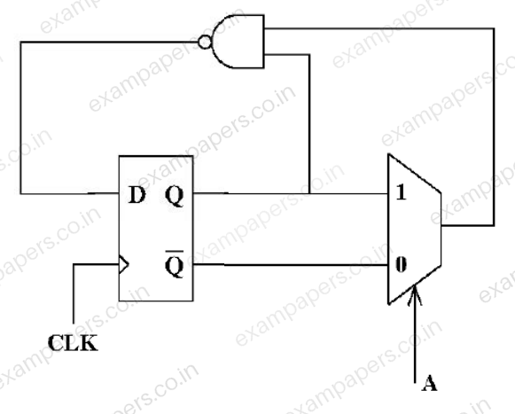
Your answerChoose one option.
Log in to check the answer
You can attempt this question now. Sign in to view the answer key, explanations and discussion.Log in to check answerQuestion 40
Open questionECMCQ2 marksNeeds review
In the circuits shown, the threshold voltage of each nMOS transistor is 0.6 V. Ignoring the effect of channel length modulation and body bias, the values of Vout1 and Vout2, respectively, in volts, are
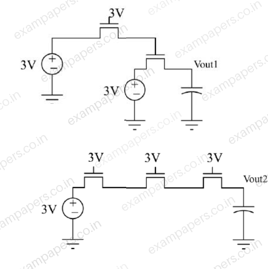
Your answerChoose one option.
Log in to check the answer
You can attempt this question now. Sign in to view the answer key, explanations and discussion.Log in to check answer