
Electrical Engineering
GATE EE concept:transfer-function PYQs
Build your understanding with focused practice from past exam papers.
How to practice concept:transfer-function
Attempt a question, record the concept and assumptions, then check the available answer. Rework mistakes after revising the relevant concepts. Topic tags can overlap; review the question context.
Questions 1–10 of 29. Imported answers require independent review unless marked reviewed.
Question 29
Open questionEEMCQ1 markNeeds review
The asymptotic Bode magnitude plot of a system is shown.
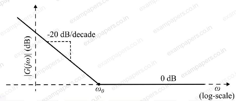
Which one of the following options best represents the transfer function of the system?
Your answerChoose one option.
Log in to check the answer
You can attempt this question now. Sign in to view the answer key, explanations and discussion.Log in to check answerQuestion 52
Open questionEEMCQ2 marksNeeds review
A system is characterized by the following state equation and output equation (
: input,
: state vector,
: output)
What are the values of
and
for which the poles of the transfer function are at
and
?Your answerChoose one option.
Log in to check the answer
You can attempt this question now. Sign in to view the answer key, explanations and discussion.Log in to check answerQuestion 29
Open questionEEMSQ1 markNeeds review
The open loop transfer function of the system shown in the figure, is
. For
, which of the following real axis point(s) is/are on the root locus? 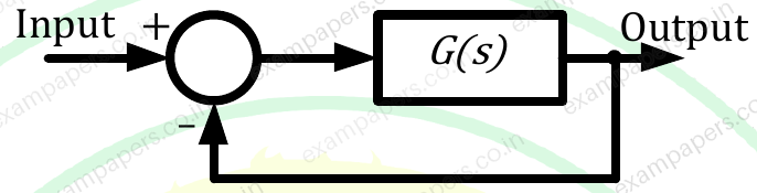
Your answerSelect all correct options. You can choose more than one.
Log in to check the answer
You can attempt this question now. Sign in to view the answer key, explanations and discussion.Log in to check answerQuestion 20
Open questionEEMCQ1 markNeeds review
For the block-diagram shown in the figure, the transfer function
is
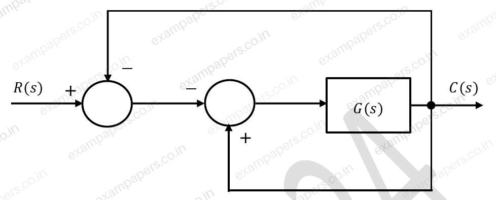
Your answerChoose one option.
Log in to check the answer
You can attempt this question now. Sign in to view the answer key, explanations and discussion.Log in to check answerQuestion 12
Open questionEEMCQ1 markNeeds review
For the block diagram shown in the figure, the transfer function
is 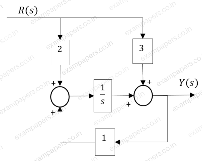
Your answerChoose one option.
Log in to check the answer
You can attempt this question now. Sign in to view the answer key, explanations and discussion.Log in to check answerQuestion 13
Open questionEEMCQ1 markNeeds review
In the Nyquist plot of the open-loop transfer function
correspond to the feedback loop shown in the figure, the infinite semi-circular arc of the Nyquist contour in
-plane is mapped into a point at 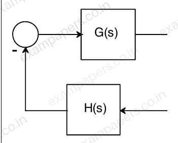
Your answerChoose one option.
Log in to check the answer
You can attempt this question now. Sign in to view the answer key, explanations and discussion.Log in to check answerQuestion 36
Open questionEEMCQ2 marksNeeds review
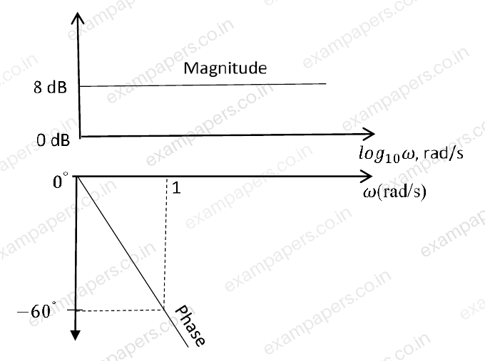
The magnitude and phase plots of an LTI system are shown in the figure. The transfer function of the system is
Your answerChoose one option.
Log in to check the answer
You can attempt this question now. Sign in to view the answer key, explanations and discussion.Log in to check answerQuestion 11
Open questionEEMCQ1 markNeeds review
The transfer function of a real system,
, is given as:
,where
,
,
and
are positive constants. This system cannot operate asYour answerChoose one option.
Log in to check the answer
You can attempt this question now. Sign in to view the answer key, explanations and discussion.Log in to check answerQuestion 19
Open questionEEMCQ1 markNeeds review
The open loop transfer function of a unity gain negative feedback system is given by
. The range of
for which the system is stable, isYour answerChoose one option.
Log in to check the answer
You can attempt this question now. Sign in to view the answer key, explanations and discussion.Log in to check answerQuestion 38
Open questionEEMCQ2 marksNeeds review
The open loop transfer function of a unity gain negative feedback system is given as
. The Nyquist contour in the s-plane encloses the entire right half plane and a small neighbourhood around the origin in the left half plane, as shown in the figure below. The number of encirclements of the point (
) by the Nyquist plot of
, corresponding to the Nyquist contour, is denoted as
. Then
equals to 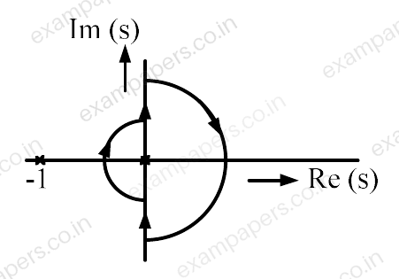
Your answerChoose one option.
Log in to check the answer
You can attempt this question now. Sign in to view the answer key, explanations and discussion.Log in to check answer