
Electrical Engineering
GATE EE concept:voltage PYQs
Build your understanding with focused practice from past exam papers.
How to practice concept:voltage
Attempt a question, record the concept and assumptions, then check the available answer. Rework mistakes after revising the relevant concepts. Topic tags can overlap; review the question context.
Questions 1–10 of 61. Imported answers require independent review unless marked reviewed.
Question 19
Open questionEEMCQ1 markNeeds review
The initial three-phase voltage phasors (
,
, and
) at a bus of a power network are as shown in Case-1. Due to a disturbance, the bus voltage phasors changed in phase by a small angle
, and the magnitudes remained the same as depicted in Case-2. 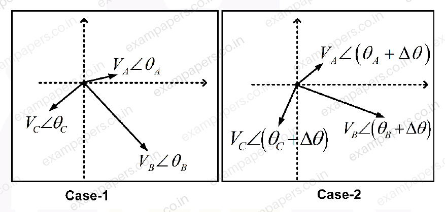
Which one of the following statements is correct about the zero sequence components?
Your answerChoose one option.
Log in to check the answer
You can attempt this question now. Sign in to view the answer key, explanations and discussion.Log in to check answerQuestion 28
Open questionEEMCQ1 markNeeds review
Consider the circuit shown in Figure (a). A gate pulse
is applied between time instants
and
. After
, during the MOSFET turn OFF process, it experiences a voltage overshoot.Based on the
waveforms shown in Figure (b), which one of the following options is correct? 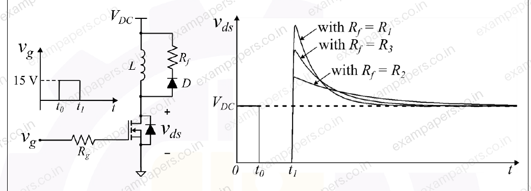
Your answerChoose one option.
Log in to check the answer
You can attempt this question now. Sign in to view the answer key, explanations and discussion.Log in to check answerQuestion 34
Open questionEENAT1 markNeeds review
Consider the circuit shown. Assume that the diode D is ideal. The supply voltage
V,
, and
. The peak diode current (in amperes) is ______________(Round off to one decimal place)
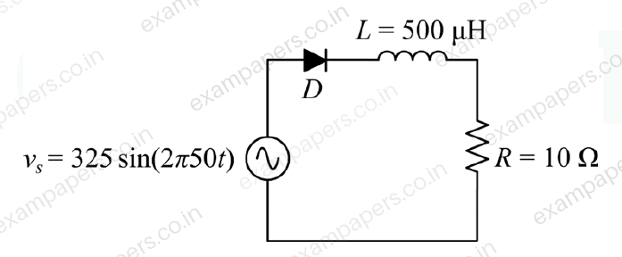
Log in to check the answer
You can attempt this question now. Sign in to view the answer key, explanations and discussion.Log in to check answerQuestion 41
Open questionEEMCQ2 marksNeeds review
A three-phase two-winding transformer has a voltage transformation ratio
, where
is the primary side voltage in p.u., and
is the secondary side voltage in p.u.
and
represent the currents injected into the primary and secondary sides of the transformer, respectively. The admittance corresponding to the leakage impedance of the transformer referred to the secondary is
p.u. Neglect the magnetizing branch. 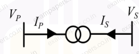
The Y bus representation of this transformer is:
Your answerChoose one option.
Log in to check the answer
You can attempt this question now. Sign in to view the answer key, explanations and discussion.Log in to check answerQuestion 47
Open questionEEMCQ2 marksNeeds review
Consider the single-phase voltage source inverter circuit feeding an inductive load (L). Assume that the power MOSFET switches are ideal. S₁ and S₂ are switched on during the first 10 μs, and S₃ and S₄ are switched on during the next 10 μs in a switching cycle. The switches in the same leg are thus switched in a complementary fashion. Neglect the dead time. The waveform of the inductor current (i_L) in the steady state is triangular with a peak value of 5 A as shown.
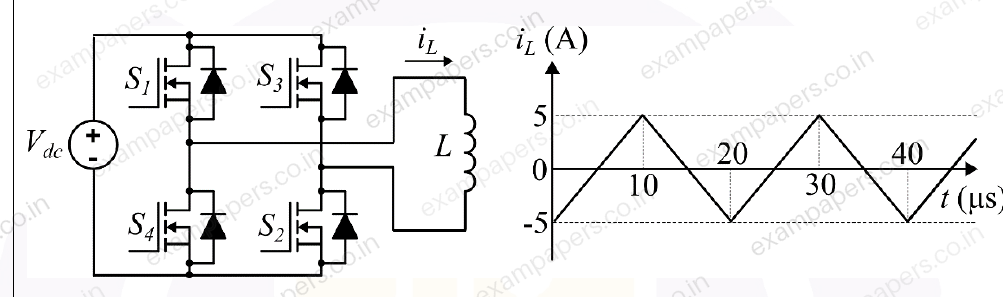
The rms value of the current through the switch S₁ is:
Your answerChoose one option.
Log in to check the answer
You can attempt this question now. Sign in to view the answer key, explanations and discussion.Log in to check answerQuestion 48
Open questionEEMCQ2 marksNeeds review
Consider the boost converter circuit shown. Assume that the semiconductor devices are ideal. In steady state, the inductor current rises linearly from 0 A to 6 A in the first 10
and then falls linearly from 6 A to 0 A in the next 10
of every switching cycle as shown. The load resistance R is 10
and the capacitance C is 500
. 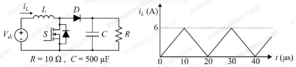
Neglect the ripple in the output voltage. What is the input voltage
?Your answerChoose one option.
Log in to check the answer
You can attempt this question now. Sign in to view the answer key, explanations and discussion.Log in to check answerQuestion 27
Open questionEEMCQ1 markNeeds review
The input voltage
and current
of a converter are given by,
where,
. The input power factor of the converter is closest toYour answerChoose one option.
Log in to check the answer
You can attempt this question now. Sign in to view the answer key, explanations and discussion.Log in to check answerQuestion 32
Open questionEENAT1 markNeeds review
Consider a distribution feeder, with
ratio of 5. At the receiving end, a 350 kVA load is connected. The maximum voltage drop will occur from the sending end to the receiving end, when the power factor of the load is __________ (round off to three decimal places).Log in to check the answer
You can attempt this question now. Sign in to view the answer key, explanations and discussion.Log in to check answerQuestion 33
Open questionEENAT1 markNeeds review
The bus impedance matrix of a 3-bus system (in pu) is
. A symmetrical fault (through a fault impedance of
pu) occurs at bus 2. Neglecting pre-fault loading conditions, the voltage at bus 1, during the fault is ______ pu (round off to three decimal places).Log in to check the answer
You can attempt this question now. Sign in to view the answer key, explanations and discussion.Log in to check answerQuestion 46
Open questionEEMCQ2 marksNeeds review
The 3-phase modulating waveforms
and
, used in sinusoidal PWM in a Voltage Source Inverter (VSI) are
where
is the fundamental frequency. The modulating waveforms are compared with a 10 kHz triangular carrier whose magnitude varies between +1 and −1. The VSI has a DC link voltage of 600 V and feeds a star connected motor. The per phase fundamental RMS motor voltage, in volts, is closest toYour answerChoose one option.
Log in to check the answer
You can attempt this question now. Sign in to view the answer key, explanations and discussion.Log in to check answer