
Electrical Engineering
GATE EE concept:voltage PYQs
Build your understanding with focused practice from past exam papers.
Questions 11–20 of 61. Imported answers require independent review unless marked reviewed.
Question 47
Open questionEEMCQ2 marksNeeds review
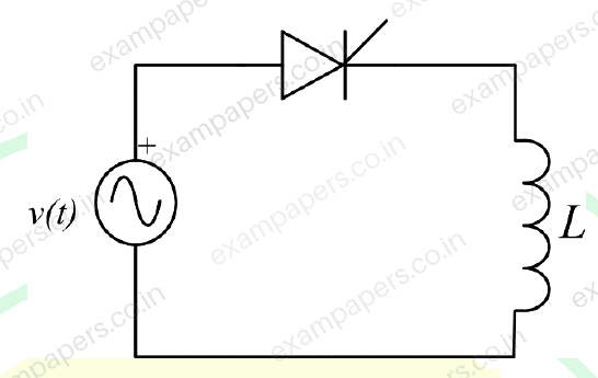
An ideal sinusoidal voltage source
feeds an ideal inductor
through an ideal SCR with firing angle
. If
, then the peak of the inductor current, in ampere, is closest to
Your answerChoose one option.
Log in to check the answer
You can attempt this question now. Sign in to view the answer key, explanations and discussion.Log in to check answerQuestion 48
Open questionEEMCQ2 marksNeeds review
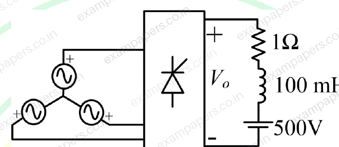
In the following circuit, the average voltage
where
is the firing angle. If the power dissipated in the resistor is 64 W, then the closest value of
in degrees is
Your answerChoose one option.
Log in to check the answer
You can attempt this question now. Sign in to view the answer key, explanations and discussion.Log in to check answerQuestion 60
Open questionEENAT2 marksNeeds review
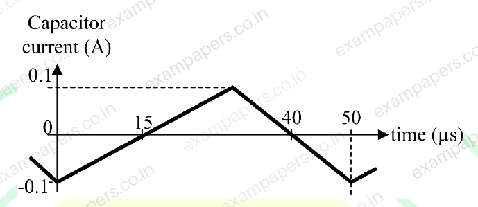
The steady state capacitor current of a conventional DC-DC buck converter, working in CCM, is shown in one switching cycle. If the input voltage is 30 V, the value of the inductor used, in mH, is ______________ (round off to one decimal place).
Log in to check the answer
You can attempt this question now. Sign in to view the answer key, explanations and discussion.Log in to check answerQuestion 28
Open questionEEMCQ1 markNeeds review
A single-phase triac based AC voltage controller feeds a series RL load. The input AC supply is 230 V, 50 Hz. The values of R and L are 10
and 18.37 mH, respectively. The minimum triggering angle of the triac to obtain controllable output voltage isYour answerChoose one option.
Log in to check the answer
You can attempt this question now. Sign in to view the answer key, explanations and discussion.Log in to check answerQuestion 41
Open questionEEMCQ2 marksNeeds review
For the three-bus lossless power network shown in the figure, the voltage magnitudes at all the buses are equal to 1 per unit (pu), and the differences of the voltage phase angles are very small. The line reactances are marked in the figure, where
,
,
, and
are strictly positive. The bus injections
and
are in pu. If
, where
, and the real power flow from bus 1 to bus 2 is 0 pu, then which one of the following options is correct? 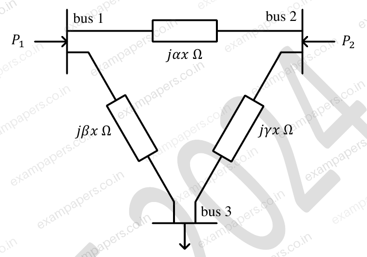
Your answerChoose one option.
Log in to check the answer
You can attempt this question now. Sign in to view the answer key, explanations and discussion.Log in to check answerQuestion 46
Open questionEEMSQ2 marksNeeds review
For a two-phase network, the phase voltages
and
are to be expressed in terms of sequence voltages
and
as
. The possible option(s) for matrix
is/areYour answerSelect all correct options. You can choose more than one.
Log in to check the answer
You can attempt this question now. Sign in to view the answer key, explanations and discussion.Log in to check answerQuestion 47
Open questionEEMSQ2 marksNeeds review
Which of the following options is/are correct for the Automatic Generation Control (AGC) and Automatic Voltage Regulator (AVR) installed with synchronous generators?
Your answerSelect all correct options. You can choose more than one.
Log in to check the answer
You can attempt this question now. Sign in to view the answer key, explanations and discussion.Log in to check answerQuestion 63
Open questionEENAT2 marksNeeds review
A single-phase full bridge voltage source inverter (VSI) feeds a purely inductive load. The inverter output voltage is a square wave in 180° conduction mode. The fundamental frequency of the output voltage is 50 Hz. If the DC input voltage of the inverter is 100 V and the value of the load inductance is 20 mH, the peak-to-peak load current in amperes is ______ (rounded off to the nearest integer).
Log in to check the answer
You can attempt this question now. Sign in to view the answer key, explanations and discussion.Log in to check answerQuestion 64
Open questionEENAT2 marksNeeds review
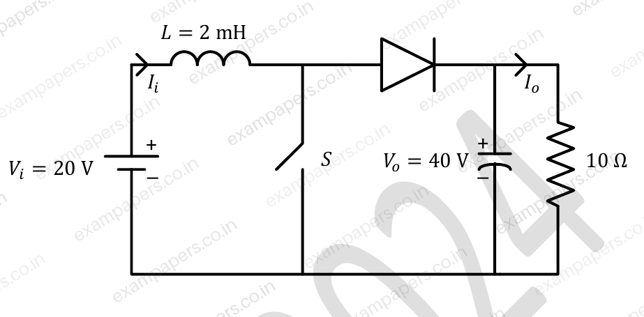
In the DC-DC converter shown in the figure, the current through the inductor is continuous. The switching frequency is 500 Hz. The voltage (
) across the load is assumed to be constant and ripple free. The peak inductor current in amperes is ______ (rounded off to the nearest integer).
Log in to check the answer
You can attempt this question now. Sign in to view the answer key, explanations and discussion.Log in to check answerQuestion 65
Open questionEENAT2 marksNeeds review
A single-phase full-controlled thyristor converter bridge is used for regenerative braking of a separately excited DC motor with the following specifications:
Specification | Value |
|---|---|
Rated armature voltage | 210 V |
Rated armature current | 10 A |
Rated speed | 1200 rpm |
Armature resistance | 1 Ω |
Input to the converter bridge | 240 V at 50 Hz |
The armature of the DC motor is fed from the full-controlled bridge and the field current is kept constant. | |
Assume that the motor is running at 600 rpm and the armature terminals of the motor are suitably reversed for regenerative braking. If the armature current of the motor is to be maintained at the rated value, the triggering angle of the converter bridge in degrees should be ______ (rounded off to 2 decimal places).
Log in to check the answer
You can attempt this question now. Sign in to view the answer key, explanations and discussion.Log in to check answer