
Electrical Engineering
GATE EE concept:voltage PYQs
Build your understanding with focused practice from past exam papers.
Questions 21–30 of 61. Imported answers require independent review unless marked reviewed.
Question 23
Open questionEEMCQ1 markNeeds review
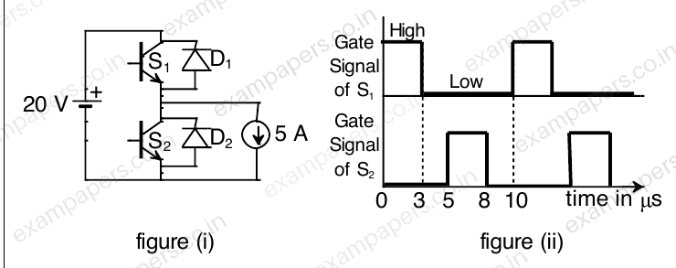
The chopper circuit shown in figure (i) feeds power to a 5 A DC constant current source. The switching frequency of the chopper is 100 kHz. All the components can be assumed to be ideal. The gate signals of switches S₁ and S₂ are shown in figure (ii). Average voltage across the 5 A current source is
Your answerChoose one option.
Log in to check the answer
You can attempt this question now. Sign in to view the answer key, explanations and discussion.Log in to check answerQuestion 26
Open questionEEMSQ1 markNeeds review
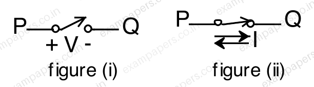
A semiconductor switch needs to block voltage V of only one polarity (V > 0) during OFF state as shown in figure (i) and carry current in both directions during ON state as shown in figure (ii). Which of the following switch combination(s) will realize the same?
Your answerSelect all correct options. You can choose more than one.
Log in to check the answer
You can attempt this question now. Sign in to view the answer key, explanations and discussion.Log in to check answerQuestion 33
Open questionEENAT1 markNeeds review
A 50 Hz, 275 kV line of length 400 km has the following parameters:
Resistance, R = 0.035 Ω/km;
Inductance, L = 1 mH/km;
Capacitance, C = 0.01 μF/km;
The line is represented by the nominal-π model. With the magnitudes of the sending end and the receiving end voltages of the line (denoted by
and
, respectively) maintained at 275 kV, the phase angle difference (
) between
and
required for maximum possible active power to be delivered to the receiving end, in degree is __________ (Round off to 2 decimal places).Log in to check the answer
You can attempt this question now. Sign in to view the answer key, explanations and discussion.Log in to check answerQuestion 41
Open questionEEMCQ2 marksNeeds review
The three-bus power system shown in the figure has one alternator connected to bus 2 which supplies 200 MW and 40 MVAr power. Bus 3 is infinite bus having a voltage of magnitude
p.u. and angle of
. A variable current source,
is connected at bus 1 and controlled such that the magnitude of the bus 1 voltage is maintained at 1.05 p.u. and the phase angle of the source current,
, where
is the phase angle of the bus 1 voltage. The three buses can be categorized for load flow analysis as 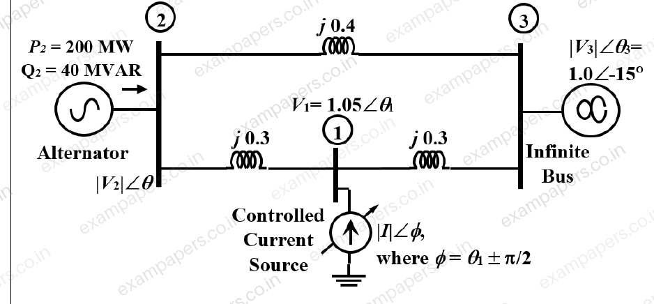
Your answerChoose one option.
Log in to check the answer
You can attempt this question now. Sign in to view the answer key, explanations and discussion.Log in to check answerQuestion 58
Open questionEENAT2 marksNeeds review
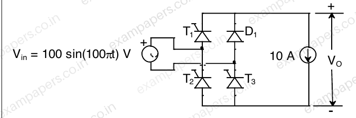
The single phase rectifier consisting of three thyristors T₁, T₂, T₃ and a diode D₁ feed power to a 10 A constant current load. T₁ and T₃ are fired at α = 60° and T₂ is fired at α = 240°. The reference for α is the positive zero crossing of vᵢₙ. The average voltage Vₒ across the load in volts is _____ (Round off to 2 decimal places).
Log in to check the answer
You can attempt this question now. Sign in to view the answer key, explanations and discussion.Log in to check answerQuestion 33
Open questionEENAT1 markNeeds review
The voltage at the input of an AC-DC rectifier is given by
where
rad/s. The input current drawn by the rectifier is given by
The input power factor, (rounded off to two decimal places), is __________________ lag.
Log in to check the answer
You can attempt this question now. Sign in to view the answer key, explanations and discussion.Log in to check answerQuestion 58
Open questionEENAT2 marksNeeds review
Consider an ideal full-bridge single-phase DC-AC inverter with a DC bus voltage magnitude of 1000 V. The inverter output voltage
shown below, is obtained when diagonal switches of the inverter are switched with 50 % duty cycle. The inverter feeds a load with a sinusoidal current given by,
A, where
. The active power, in watts, delivered to the load is ________. (round off to nearest integer) 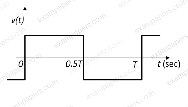
Log in to check the answer
You can attempt this question now. Sign in to view the answer key, explanations and discussion.Log in to check answerQuestion 60
Open questionEENAT2 marksNeeds review
A 3-phase grid-connected voltage source converter with DC link voltage of 1000 V is switched using sinusoidal Pulse Width Modulation (PWM) technique. If the grid phase current is 10 A and the 3-phase complex power supplied by the converter is given by
VA, then the modulation index used in sinusoidal PWM is __________. (round off to two decimal places)Log in to check the answer
You can attempt this question now. Sign in to view the answer key, explanations and discussion.Log in to check answerQuestion 61
Open questionEENAT2 marksNeeds review
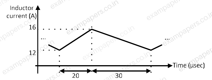
The steady state current flowing through the inductor of a DC-DC buck boost converter is given in the figure below. If the peak-to-peak ripple in the output voltage of the converter is 1 V, then the value of the output capacitor, in μF, is ________________. (round off to nearest integer)
Log in to check the answer
You can attempt this question now. Sign in to view the answer key, explanations and discussion.Log in to check answerQuestion 24
Open questionEENAT1 markNeeds review
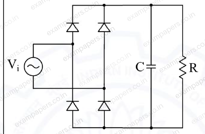
In the circuit shown, the input
is a sinusoidal AC voltage having an RMS value of
. The worst-case peak-inverse voltage seen across any diode is _____ V. (Round off to 2 decimal places.)
Log in to check the answer
You can attempt this question now. Sign in to view the answer key, explanations and discussion.Log in to check answer