
Electrical Engineering
GATE EE Network elements PYQs
Build your understanding with focused practice from past exam papers.
How to practice Network elements
Attempt a question, record the concept and assumptions, then check the available answer. Rework mistakes after revising the relevant concepts. Topic tags can overlap; review the question context.
Questions 1–10 of 49. Imported answers require independent review unless marked reviewed.
Question 23
Open questionEEMCQ1 markNeeds review
A circuit with ideal elements is shown.
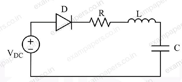
Which one of the following options correctly identifies all the linear elements in the circuit?
Your answerChoose one option.
Log in to check the answer
You can attempt this question now. Sign in to view the answer key, explanations and discussion.Log in to check answerQuestion 24
Open questionEEMCQ1 markNeeds review
For the circuit shown, which one of the following options correctly identifies the Thevenin’s equivalent parameters between nodes Y and Z?
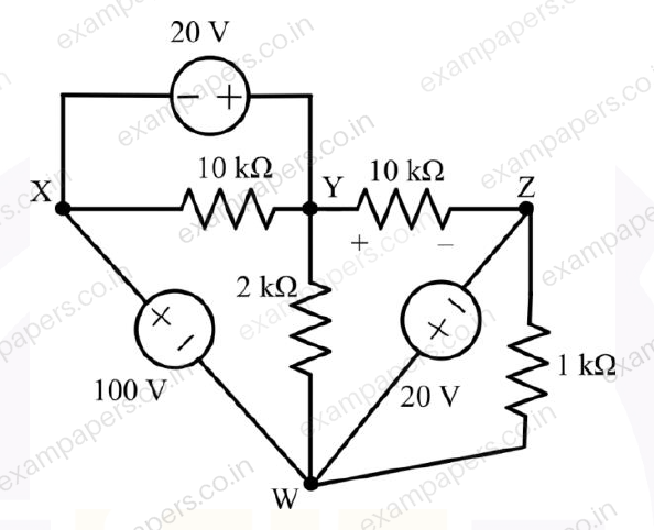
Your answerChoose one option.
Log in to check the answer
You can attempt this question now. Sign in to view the answer key, explanations and discussion.Log in to check answerQuestion 25
Open questionEEMCQ1 markNeeds review
Refer to the four circuits shown. The top-left circuit shows a voltage source
and a dependent voltage source
; the top-right circuit shows a voltage source
and a dependent current source
; the bottom-left circuit shows a current source
and a dependent voltage source
; and the bottom-right circuit shows a current source
and a dependent current source
. Which one of the following options for
,
,
, and
makes all of them realizable? 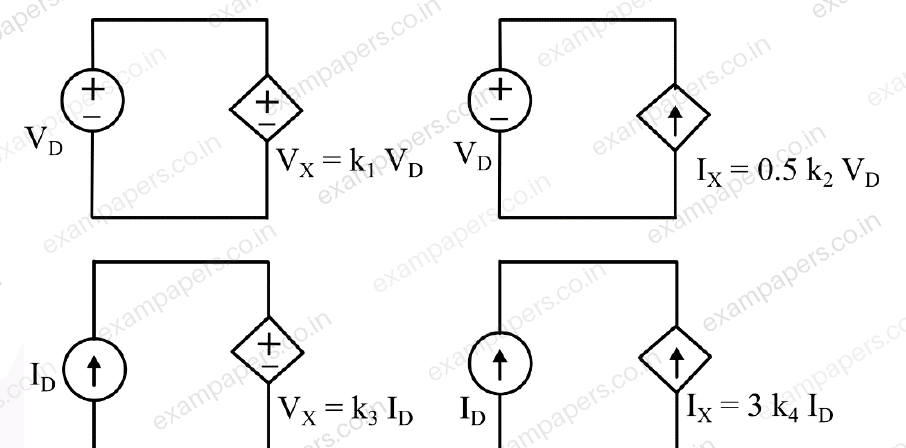
Your answerChoose one option.
Log in to check the answer
You can attempt this question now. Sign in to view the answer key, explanations and discussion.Log in to check answerQuestion 26
Open questionEEMCQ1 markNeeds review
A single-phase voltage source
V delivers a current,
A to a load. The load power factor, correct up to two decimal places, is:Your answerChoose one option.
Log in to check the answer
You can attempt this question now. Sign in to view the answer key, explanations and discussion.Log in to check answerQuestion 42
Open questionEEMCQ2 marksNeeds review
An electrical component has voltage drop
, when the current through it is
. What is the average power dissipated over a half cycle corresponding to
?Your answerChoose one option.
Log in to check the answer
You can attempt this question now. Sign in to view the answer key, explanations and discussion.Log in to check answerQuestion 43
Open questionEEMCQ2 marksNeeds review
The electrical network shown has an independent voltage source (10 V) and a current source (1 u(t) mA).
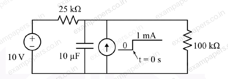
The voltage across the capacitor at time instants (in seconds)
,
, and
, respectively, is:Your answerChoose one option.
Log in to check the answer
You can attempt this question now. Sign in to view the answer key, explanations and discussion.Log in to check answerQuestion 44
Open questionEEMCQ2 marksNeeds review
The terminal voltage and current of a linear electrical network shown in Figure (a) are given in the table.
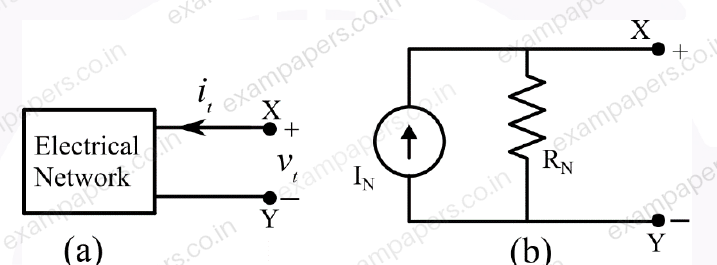
The correct choice for the parameters
of the Norton equivalent circuit shown in Figure (b) is:Your answerChoose one option.
Log in to check the answer
You can attempt this question now. Sign in to view the answer key, explanations and discussion.Log in to check answerQuestion 60
Open questionEENAT2 marksNeeds review
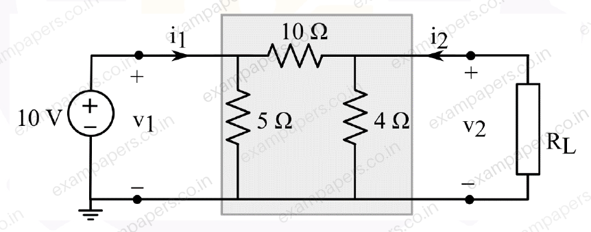
Consider the two-port network shown. For maximum power transfer to the resistive load (R_L), the value of R_L should be _________ Ω (Round off to two decimal places)
Log in to check the answer
You can attempt this question now. Sign in to view the answer key, explanations and discussion.Log in to check answerQuestion 18
Open questionEEMCQ1 markNeeds review
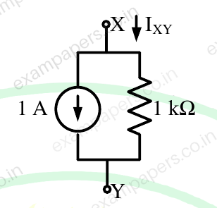
The I-V characteristics of the element between the nodes X and Y is best depicted by
Your answerChoose one option.
Log in to check the answer
You can attempt this question now. Sign in to view the answer key, explanations and discussion.Log in to check answerQuestion 19
Open questionEEMCQ1 markNeeds review
A nullator is defined as a circuit element where the voltage across the device and the current through the device are both zero. A series combination of a nullator and a resistor of value, R, will behave as a
Your answerChoose one option.
Log in to check the answer
You can attempt this question now. Sign in to view the answer key, explanations and discussion.Log in to check answer