
Electrical Engineering
GATE EE Network elements PYQs
Build your understanding with focused practice from past exam papers.
Questions 11–20 of 49. Imported answers require independent review unless marked reviewed.
Question 39
Open questionEEMCQ2 marksNeeds review
In the circuit, shown below, if the values of R and C are very large, the form of the output voltage for a very high frequency square wave input, is best represented by
Your answerChoose one option.
Log in to check the answer
You can attempt this question now. Sign in to view the answer key, explanations and discussion.Log in to check answerQuestion 57
Open questionEENAT2 marksNeeds review
The switch (S) closes at
sec. The time, in sec, the capacitor takes to charge to 50 V is _____ (round off to one decimal place). 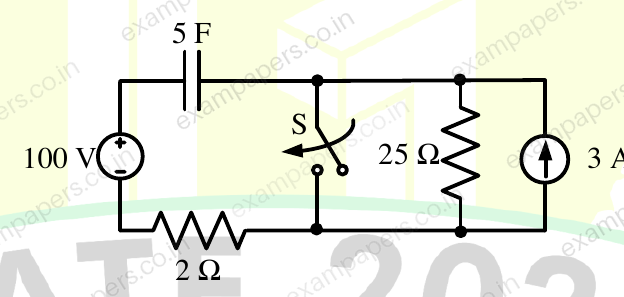
Log in to check the answer
You can attempt this question now. Sign in to view the answer key, explanations and discussion.Log in to check answerQuestion 58
Open questionEENAT2 marksNeeds review
In an experiment to measure the active power drawn by a single-phase RL Load connected to an AC source through a 2
resistor, three voltmeters are connected as shown in the figure below. The voltmeter readings are as follows:
,
,
. Assuming perfect resistors and ideal voltmeters, the Load-active power measured in this experiment, in W, is _______ (round off to one decimal place). 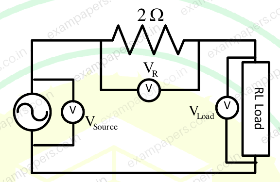
Log in to check the answer
You can attempt this question now. Sign in to view the answer key, explanations and discussion.Log in to check answerQuestion 12
Open questionEEMCQ1 markNeeds review
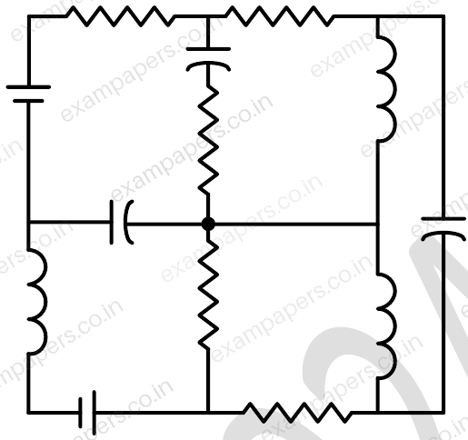
The number of junctions in the circuit is
Your answerChoose one option.
Log in to check the answer
You can attempt this question now. Sign in to view the answer key, explanations and discussion.Log in to check answerQuestion 13
Open questionEEMCQ1 markNeeds review
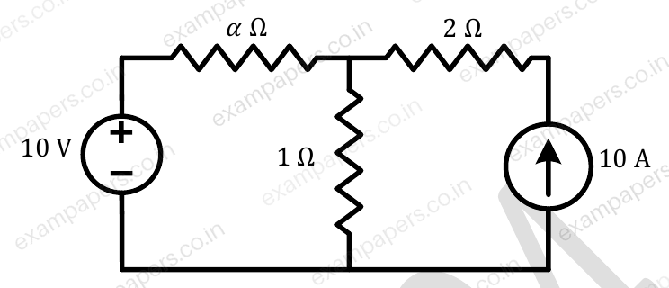
All the elements in the circuit are ideal. The power derived by the 10 V source in watts is
Your answerChoose one option.
Log in to check the answer
You can attempt this question now. Sign in to view the answer key, explanations and discussion.Log in to check answerQuestion 14
Open questionEEMCQ1 markNeeds review
The circuit shown in the figure with the switch
open, is in steady state. After the switch
is closed, the time constant of the circuit in seconds is 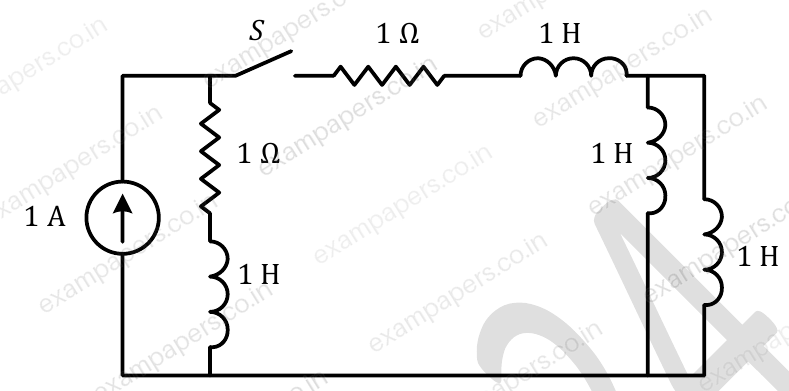
Your answerChoose one option.
Log in to check the answer
You can attempt this question now. Sign in to view the answer key, explanations and discussion.Log in to check answerQuestion 48
Open questionEENAT2 marksNeeds review
Two passive two-port networks P and Q are connected as shown in the figure. The impedance matrix of network P is
. The admittance matrix of network Q is
. Let the ABCD matrix of the two-port network R in the figure be
. The value of
in
is __________ (rounded off to 2 decimal places). 
Log in to check the answer
You can attempt this question now. Sign in to view the answer key, explanations and discussion.Log in to check answerQuestion 49
Open questionEENAT2 marksNeeds review
For the circuit shown in the figure, the source frequency is 5000 rad/sec. The mutual inductance between the magnetically coupled inductors is 5 mH with their self inductances being 125 mH and 1 mH. The Thevenin’s impedance,
, between the terminals P and Q in
is ________ (rounded off to 2 decimal places). 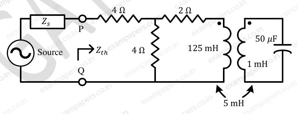
Log in to check the answer
You can attempt this question now. Sign in to view the answer key, explanations and discussion.Log in to check answerQuestion 50
Open questionEENAT2 marksNeeds review
In the circuit shown,
and
. It is supplied by a three phase 400 V source with the phase sequence being R-Y-B. Assume the watt meters
and
to be ideal. The magnitude of the difference between the readings of
and
in watts is __________ (rounded off to 2 decimal places). 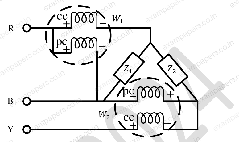
Log in to check the answer
You can attempt this question now. Sign in to view the answer key, explanations and discussion.Log in to check answerQuestion 29
Open questionEENAT1 markNeeds review
The value of parameters of the circuit shown in the figure are
For time
, the circuit is at steady state with the switch ‘K’ in closed condition. If the switch is opened at
, the value of the voltage across the inductor (
) at
in Volts is __________ (Round off to 1 decimal place). 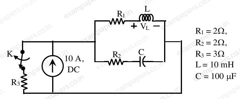
Log in to check the answer
You can attempt this question now. Sign in to view the answer key, explanations and discussion.Log in to check answer