
Electrical Engineering
GATE EE topic:electric-circuits PYQs
Build your understanding with focused practice from past exam papers.
Questions 11–20 of 22. Imported answers require independent review unless marked reviewed.
Question 32
Open questionEEMCQ2 marksNeeds review
The equivalent impedance
for the infinite ladder circuit shown in the figure is 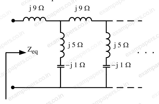
Your answerChoose one option.
Log in to check the answer
You can attempt this question now. Sign in to view the answer key, explanations and discussion.Log in to check answerQuestion 47
Open questionEENAT2 marksNeeds review
A three-phase load is connected to a three-phase balanced supply as shown in the figure. If
,
and
(angles are considered positive in the anti-clockwise direction), the value of
for zero current in the neutral wire is __________
(up to 2 decimal places). 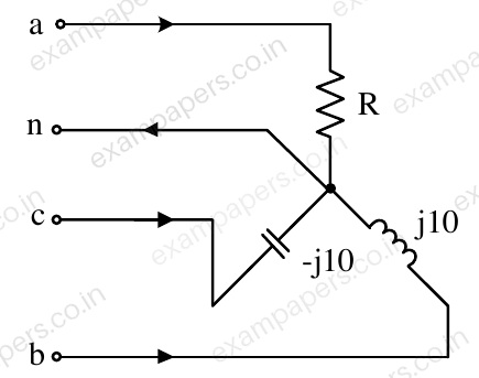
Log in to check the answer
You can attempt this question now. Sign in to view the answer key, explanations and discussion.Log in to check answerQuestion 48
Open questionEENAT2 marksNeeds review
The voltage across the circuit in the figure, and the current through it, are given by the following expressions:
where
radians. If the average power delivered to the circuit is zero, then the value of
(in Ampere) is ____ (up to 2 decimal places). 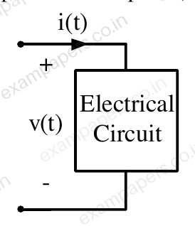
Log in to check the answer
You can attempt this question now. Sign in to view the answer key, explanations and discussion.Log in to check answerQuestion 55
Open questionEENAT2 marksNeeds review
The voltage
across the terminals a and b as shown in the figure, is a sinusoidal voltage having a frequency
radian/s. When the inductor current
is in phase with the voltage
, the magnitude of the impedance
(in
) seen between the terminals a and b is ________ (up to 2 decimal places). 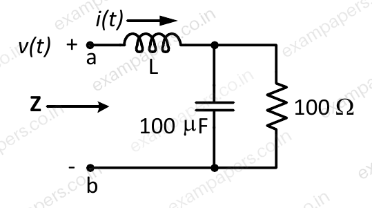
Log in to check the answer
You can attempt this question now. Sign in to view the answer key, explanations and discussion.Log in to check answerQuestion 9
Open questionEEMCQ1 markNeeds review
A source is supplying a load through a 2-phase, 3-wire transmission system as shown in figure below. The instantaneous voltage and current in phase-a are
V and
A, respectively. Similarly for phase-b, the instantaneous voltage and current are
V and
A, respectively. The total instantaneous power flowing from the source to the load is 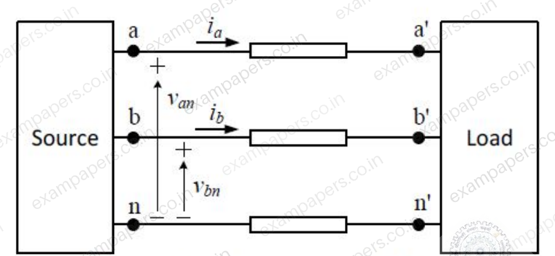
Your answerChoose one option.
Log in to check the answer
You can attempt this question now. Sign in to view the answer key, explanations and discussion.Log in to check answerQuestion 18
Open questionEENAT1 markNeeds review
The power supplied by the 25 V source in the figure shown below is ________ W.
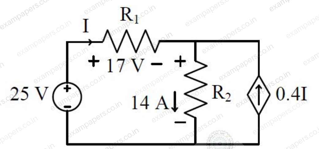
Log in to check the answer
You can attempt this question now. Sign in to view the answer key, explanations and discussion.Log in to check answerQuestion 19
Open questionEENAT1 markNeeds review
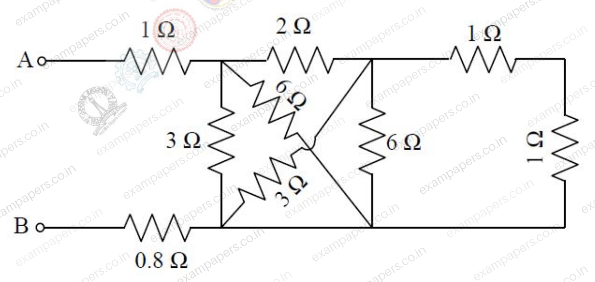
The equivalent resistance between the terminals A and B is ________
. 
Log in to check the answer
You can attempt this question now. Sign in to view the answer key, explanations and discussion.Log in to check answerQuestion 29
Open questionEEMCQ2 marksNeeds review
Two passive two-port networks are connected in cascade as shown in figure. A voltage source is connected at port 1.
Given
and
are the generalized circuit constants. If the Thevenin equivalent circuit at port 3 consists of a voltage source
and an impedance
, connected in series, then 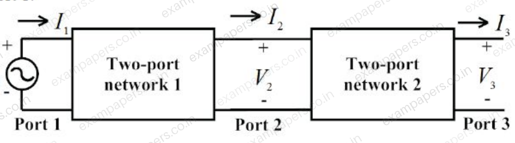
Your answerChoose one option.
Log in to check the answer
You can attempt this question now. Sign in to view the answer key, explanations and discussion.Log in to check answerQuestion 34
Open questionEEMCQ2 marksNeeds review
The load shown in the figure is supplied by a 400 V (line-to-line), 3-phase source (RYB sequence). The load is balanced and inductive, drawing 3464 VA. When the switch S is in position N, the three watt-meters
,
and
read 577.35 W each. If the switch is moved to position Y, the readings of the watt-meters in watts will be: 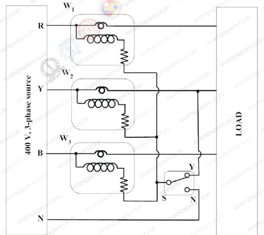
Your answerChoose one option.
Log in to check the answer
You can attempt this question now. Sign in to view the answer key, explanations and discussion.Log in to check answerQuestion 39
Open questionEEMCQ2 marksNeeds review
A load is supplied by a 230 V, 50 Hz source. The active power P and the reactive power Q consumed by the load are such that 1 kW ≤ P ≤ 2 kW and 1 kVAR ≤ Q ≤ 2 kVAR. A capacitor connected across the load for power factor correction generates 1 kVAR reactive power. The worst case power factor after power factor correction is
Your answerChoose one option.
Log in to check the answer
You can attempt this question now. Sign in to view the answer key, explanations and discussion.Log in to check answer