
Electrical Engineering
GATE EE topic:electrical-machines PYQs
Build your understanding with focused practice from past exam papers.
Questions 661–670 of 715. Imported answers require independent review unless marked reviewed.
Question 38
Open questionEE-2MCQ2 marksNeeds review
For the circuit shown below, assume that the OPAMP is ideal.
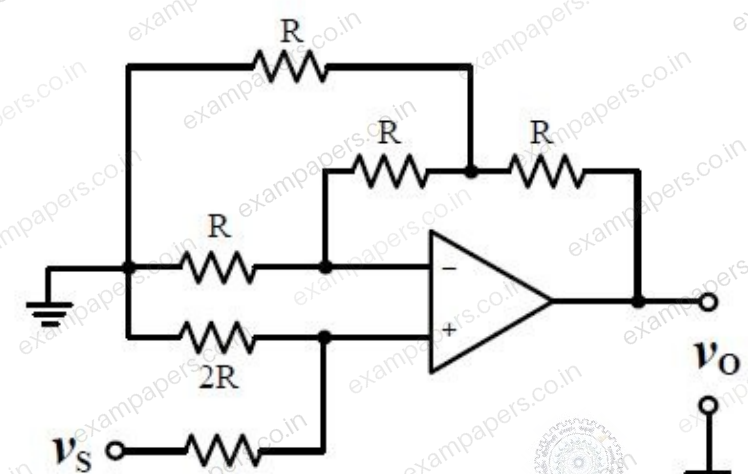
Which one of the following is TRUE?
Your answerChoose one option.
Log in to check the answer
You can attempt this question now. Sign in to view the answer key, explanations and discussion.Log in to check answerQuestion 39
Open questionEEMCQ2 marksNeeds review
A load is supplied by a 230 V, 50 Hz source. The active power P and the reactive power Q consumed by the load are such that 1 kW ≤ P ≤ 2 kW and 1 kVAR ≤ Q ≤ 2 kVAR. A capacitor connected across the load for power factor correction generates 1 kVAR reactive power. The worst case power factor after power factor correction is
Your answerChoose one option.
Log in to check the answer
You can attempt this question now. Sign in to view the answer key, explanations and discussion.Log in to check answerQuestion 39
Open questionEE-2MCQ2 marksNeeds review
The figure below shows a half-bridge voltage source inverter supplying an RL-load with
and
. The desired fundamental frequency of the load voltage is 50 Hz. The switch control signals of the converter are generated using sinusoidal pulse width modulation with modulation index,
. At 50 Hz, the RL-load draws an active power of 1.44 kW. The value of DC source voltage
in volts is 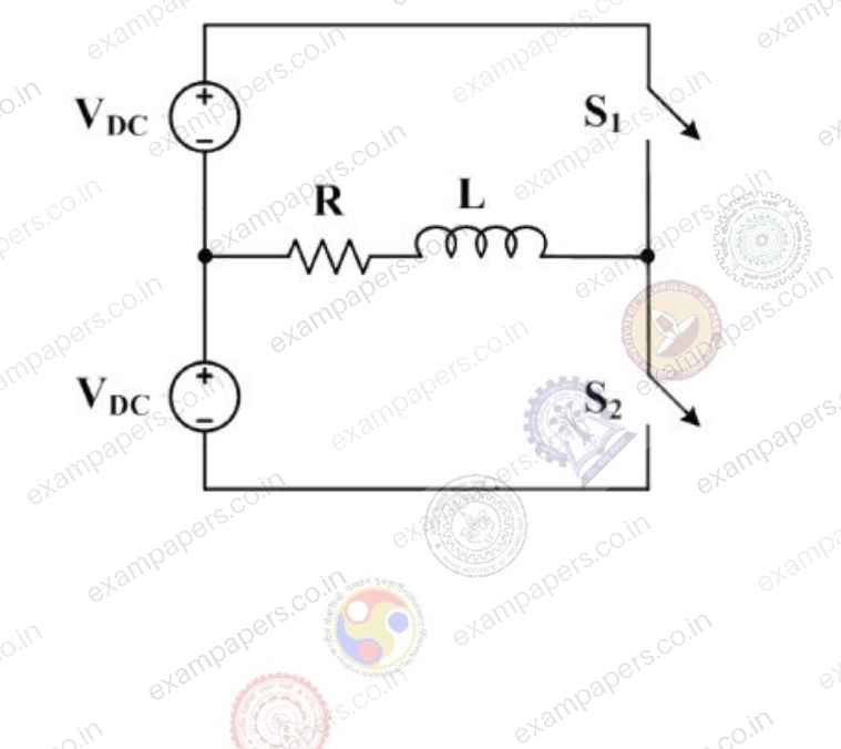
Your answerChoose one option.
Log in to check the answer
You can attempt this question now. Sign in to view the answer key, explanations and discussion.Log in to check answerQuestion 40
Open questionEEMCQ2 marksNeeds review
The bus admittance matrix for a power system network is
pu. There is a transmission line, connected between buses 1 and 3, which is represented by the circuit shown in figure.

Reactance is 0.05 pu; susceptance is 0.05 pu at each end. If this transmission line is removed from service, what is the modified bus admittance matrix?
Your answerChoose one option.
Log in to check the answer
You can attempt this question now. Sign in to view the answer key, explanations and discussion.Log in to check answerQuestion 40
Open questionEE-2MCQ2 marksNeeds review
A person decides to toss a fair coin repeatedly until he gets a head. He will make at most 3 tosses. Let the random variable
denote the number of heads. The value of
, where
denotes the variance, equalsYour answerChoose one option.
Log in to check the answer
You can attempt this question now. Sign in to view the answer key, explanations and discussion.Log in to check answerQuestion 41
Open questionEEMCQ2 marksNeeds review
The switch in the figure below was closed for a long time. It is opened at
. The current in the inductor of 2 H for
, is
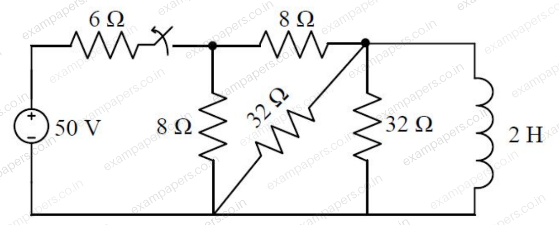
Your answerChoose one option.
Log in to check the answer
You can attempt this question now. Sign in to view the answer key, explanations and discussion.Log in to check answerQuestion 41
Open questionEE-2MCQ2 marksNeeds review
For the network given in figure below, the Thevenin’s voltage
is
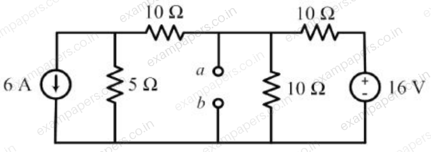
Your answerChoose one option.
Log in to check the answer
You can attempt this question now. Sign in to view the answer key, explanations and discussion.Log in to check answerQuestion 42
Open questionEENAT2 marksNeeds review
Only one of the real roots of
lies in the interval
and bisection method is used to find its value. For achieving an accuracy of 0.001, the required minimum number of iterations is _________.Log in to check the answer
You can attempt this question now. Sign in to view the answer key, explanations and discussion.Log in to check answerQuestion 42
Open questionEE-2NAT2 marksNeeds review
A 120 V DC shunt motor takes 2 A at no load. It takes 7 A on full load while running at 1200 rpm. The armature resistance is 0.8 Ω, and the shunt field resistance is 240 Ω. The no load speed, in rpm, is _____________.
Log in to check the answer
You can attempt this question now. Sign in to view the answer key, explanations and discussion.Log in to check answerQuestion 43
Open questionEENAT2 marksNeeds review
In the circuit shown below, the maximum power transferred to the resistor
is ______ W.
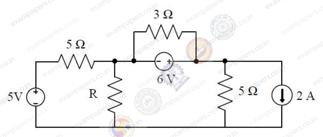
Log in to check the answer
You can attempt this question now. Sign in to view the answer key, explanations and discussion.Log in to check answer