
Electrical Engineering
GATE EE year:2018 PYQs
Build your understanding with focused practice from past exam papers.
Questions 61–65 of 65. Imported answers require independent review unless marked reviewed.
Question 51
Open questionEENAT2 marksNeeds review
A 3-phase 900 kVA,
(
/Y), 50 Hz transformer has primary (high voltage side) resistance per phase of 0.3
and secondary (low voltage side) resistance per phase of 0.02
. Iron loss of the transformer is 10 kW. The full load % efficiency of the transformer operated at unity power factor is ________ (up to 2 decimal places).Log in to check the answer
You can attempt this question now. Sign in to view the answer key, explanations and discussion.Log in to check answerQuestion 52
Open questionEENAT2 marksNeeds review
A 200 V DC series motor, when operating from rated voltage while driving a certain load, draws 10 A current and runs at 1000 r.p.m. The total series resistance is 1
. The magnetic circuit is assumed to be linear. At the same supply voltage, the load torque is increased by 44%. The speed of the motor in r.p.m. (rounded to the nearest integer) is ______.Log in to check the answer
You can attempt this question now. Sign in to view the answer key, explanations and discussion.Log in to check answerQuestion 53
Open questionEENAT2 marksNeeds review
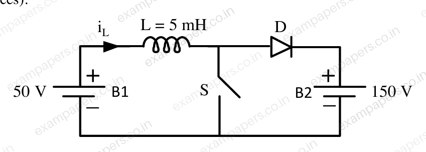
A dc to dc converter shown in the figure is charge a battery bank, B2 whose voltage is constant at 150 V. B1 is another battery bank whose voltage is constant at 50 V. The value of the inductor, L is 5 mH and the ideal switch, S is operated with a switching frequency of 5 kHz with a duty ratio of 0.4. Once the circuit has attained steady state and assuming the diode D to be ideal, the power transferred from B1 to B2 (in Watt) is __________ (up to 2 decimal places).
Log in to check the answer
You can attempt this question now. Sign in to view the answer key, explanations and discussion.Log in to check answerQuestion 54
Open questionEENAT2 marksNeeds review
The equivalent circuit of a single phase induction motor is shown in the figure, where the parameters are
,
and
is the slip. At no-load, the motor speed can be approximated to be the synchronous speed. The no-load lagging power factor of the motor is _________ (up to 3 decimal places). 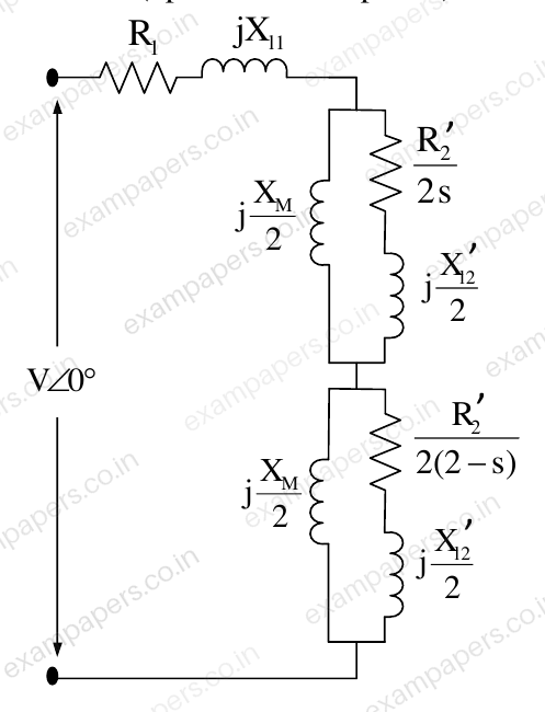
Log in to check the answer
You can attempt this question now. Sign in to view the answer key, explanations and discussion.Log in to check answerQuestion 55
Open questionEENAT2 marksNeeds review
The voltage
across the terminals a and b as shown in the figure, is a sinusoidal voltage having a frequency
radian/s. When the inductor current
is in phase with the voltage
, the magnitude of the impedance
(in
) seen between the terminals a and b is ________ (up to 2 decimal places). 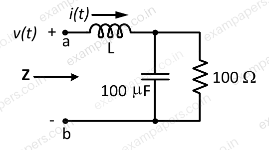
Log in to check the answer
You can attempt this question now. Sign in to view the answer key, explanations and discussion.Log in to check answer