
Electrical Engineering
GATE EE year:2021 PYQs
Build your understanding with focused practice from past exam papers.
Questions 31–40 of 65. Imported answers require independent review unless marked reviewed.
Question 21
Open questionEENAT1 markNeeds review
A signal generator having a source resistance of 50 Ω is set to generate a 1 kHz sinewave. Open circuit terminal voltage is 10 V peak-to-peak. Connecting a capacitor across the terminals reduces the voltage to 8 V peak-to-peak. The value of this capacitor is ______ μF. (Round off to 2 decimal places.)
Log in to check the answer
You can attempt this question now. Sign in to view the answer key, explanations and discussion.Log in to check answerQuestion 22
Open questionEENAT1 markNeeds review
A 16-bit synchronous binary up-counter is clocked with a frequency
. The two most significant bits are OR-ed together to form an output Y. Measurements show that Y is periodic, and the duration for which Y remains high in each period is 24 ms. The clock frequency
is ____________ MHz. (Round off to 2 decimal places.)Log in to check the answer
You can attempt this question now. Sign in to view the answer key, explanations and discussion.Log in to check answerQuestion 23
Open questionEENAT1 markNeeds review
In the BJT circuit shown, beta of the PNP transistor is 100. Assume
V. The voltage across
will be 5 V when
is ____ kΩ. (Round off to 2 decimal places.) 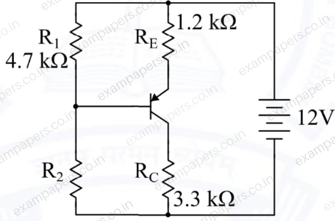
Log in to check the answer
You can attempt this question now. Sign in to view the answer key, explanations and discussion.Log in to check answerQuestion 24
Open questionEENAT1 markNeeds review
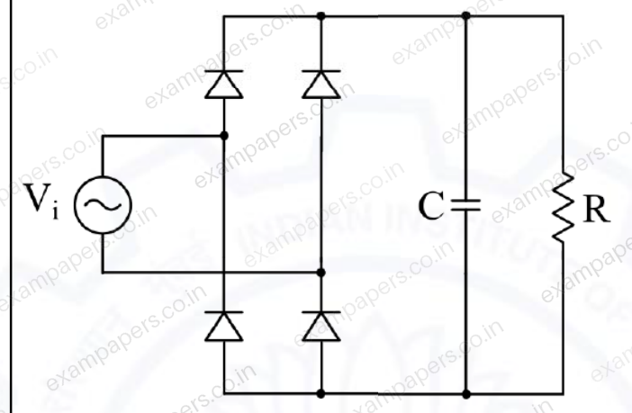
In the circuit shown, the input
is a sinusoidal AC voltage having an RMS value of
. The worst-case peak-inverse voltage seen across any diode is _____ V. (Round off to 2 decimal places.)
Log in to check the answer
You can attempt this question now. Sign in to view the answer key, explanations and discussion.Log in to check answerQuestion 25
Open questionEENAT1 markNeeds review
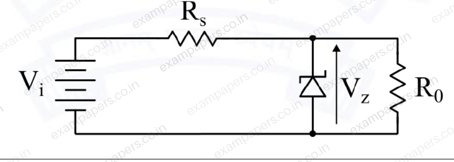
In the circuit shown, a 5 V Zener diode is used to regulate the voltage across load
. The input is an unregulated DC voltage with a minimum value of 6 V and a maximum value of 8 V. The value of
is 6
. The Zener diode has a maximum rated power dissipation of 2.5 W. Assuming the Zener diode to be ideal, the minimum value of
is _____
.
Log in to check the answer
You can attempt this question now. Sign in to view the answer key, explanations and discussion.Log in to check answerQuestion 26
Open questionEEMCQ2 marksNeeds review
In the open interval
, the polynomial
hasYour answerChoose one option.
Log in to check the answer
You can attempt this question now. Sign in to view the answer key, explanations and discussion.Log in to check answerQuestion 27
Open questionEEMCQ2 marksNeeds review
Suppose the probability that a coin toss shows “head” is
, where
. The coin is tossed repeatedly until the first “head” appears. The expected number of tosses required isYour answerChoose one option.
Log in to check the answer
You can attempt this question now. Sign in to view the answer key, explanations and discussion.Log in to check answerQuestion 28
Open questionEEMCQ2 marksNeeds review
Let
,
,
and
be the vertices of a rectangle
in the complex plane. Assuming that
is traversed in counter-clockwise direction, the value of the contour integral
isYour answerChoose one option.
Log in to check the answer
You can attempt this question now. Sign in to view the answer key, explanations and discussion.Log in to check answerQuestion 29
Open questionEEMCQ2 marksNeeds review
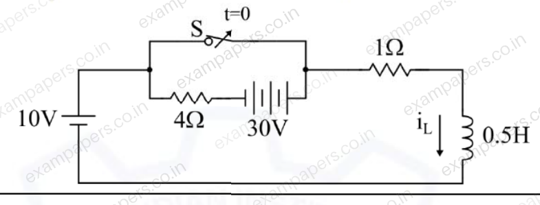
In the circuit, switch ‘S’ is in the closed position for a very long time. If the switch is opened at time
, then
in amperes, for
is
Your answerChoose one option.
Log in to check the answer
You can attempt this question now. Sign in to view the answer key, explanations and discussion.Log in to check answerQuestion 30
Open questionEEMCQ2 marksNeeds review
The input impedance,
, for the network shown is
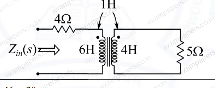
Your answerChoose one option.
Log in to check the answer
You can attempt this question now. Sign in to view the answer key, explanations and discussion.Log in to check answer