
Electrical Engineering
GATE EE year:2023 PYQs
Build your understanding with focused practice from past exam papers.
Questions 11–20 of 65. Imported answers require independent review unless marked reviewed.
Question 11
Open questionEEMCQ1 markNeeds review
For a given vector
, the vector normal to the plane defined by
isYour answerChoose one option.
Log in to check the answer
You can attempt this question now. Sign in to view the answer key, explanations and discussion.Log in to check answerQuestion 12
Open questionEEMCQ1 markNeeds review
For the block diagram shown in the figure, the transfer function
is 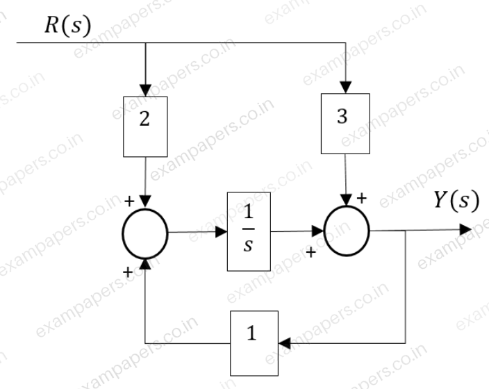
Your answerChoose one option.
Log in to check the answer
You can attempt this question now. Sign in to view the answer key, explanations and discussion.Log in to check answerQuestion 13
Open questionEEMCQ1 markNeeds review
In the Nyquist plot of the open-loop transfer function
correspond to the feedback loop shown in the figure, the infinite semi-circular arc of the Nyquist contour in
-plane is mapped into a point at 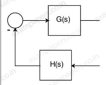
Your answerChoose one option.
Log in to check the answer
You can attempt this question now. Sign in to view the answer key, explanations and discussion.Log in to check answerQuestion 14
Open questionEEMCQ1 markNeeds review
Consider a unity-gain negative feedback system consisting of the plant
(given below) and a proportional-integral controller. Let the proportional gain and integral gain be 3 and 1, respectively. For a unit step reference input, the final values of the controller output and the plant output, respectively, are
Your answerChoose one option.
Log in to check the answer
You can attempt this question now. Sign in to view the answer key, explanations and discussion.Log in to check answerQuestion 15
Open questionEEMCQ1 markNeeds review
The following columns present various modes of induction machine operation and the ranges of slip
Column A: Mode of operation | Column B: Range of Slip |
|---|---|
a. Running in generator mode | p) From 0.0 to 1.0 |
b. Running in motor mode | q) From 1.0 to 2.0 |
c. Plugging in motor mode | r) From -1.0 to 0.0 |
The correct match between the elements in column A with those of column B is
Your answerChoose one option.
Log in to check the answer
You can attempt this question now. Sign in to view the answer key, explanations and discussion.Log in to check answerQuestion 16
Open questionEEMCQ1 markNeeds review
A 10-pole, 50 Hz, 240 V, single phase induction motor runs at 540 RPM while driving rated load. The frequency of induced rotor currents due to backward field is
Your answerChoose one option.
Log in to check the answer
You can attempt this question now. Sign in to view the answer key, explanations and discussion.Log in to check answerQuestion 17
Open questionEEMCQ1 markNeeds review
A continuous-time system that is initially at rest is described by
, where
is the input voltage and
is the output voltage. The impulse response of the system isYour answerChoose one option.
Log in to check the answer
You can attempt this question now. Sign in to view the answer key, explanations and discussion.Log in to check answerQuestion 18
Open questionEEMCQ1 markNeeds review
The Fourier transform
of the signal
is given by
Which one of the following statements is true?
Your answerChoose one option.
Log in to check the answer
You can attempt this question now. Sign in to view the answer key, explanations and discussion.Log in to check answerQuestion 19
Open questionEEMCQ1 markNeeds review
The Z-transform of a discrete signal
is
Which one of the following statements is true?
Your answerChoose one option.
Log in to check the answer
You can attempt this question now. Sign in to view the answer key, explanations and discussion.Log in to check answerQuestion 20
Open questionEEMCQ1 markNeeds review
For the three-bus power system shown in the figure, the trip signals to the circuit breakers B₁ to B₉ are provided by overcurrent relays R₁ to R₉, respectively, some of which have directional properties also. The necessary condition for the system to be protected for short circuit fault at any part of the system between bus 1 and the R-L loads with isolation of minimum portion of the network using minimum number of directional relays is
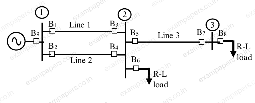
Your answerChoose one option.
Log in to check the answer
You can attempt this question now. Sign in to view the answer key, explanations and discussion.Log in to check answer