
Instrumentation Engineering
GATE IN Analog Electronics PYQs
Build your understanding with focused practice from past exam papers.
How to practice Analog Electronics
Attempt a question, record the concept and assumptions, then check the available answer. Rework mistakes after revising the relevant concepts. Topic tags can overlap; review the question context.
Questions 1–10 of 65. Imported answers require independent review unless marked reviewed.
Question 21
Open questionINMCQ1 markNeeds review
A common gate amplifier represents a ______________.
Your answerChoose one option.
Log in to check the answer
You can attempt this question now. Sign in to view the answer key, explanations and discussion.Log in to check answerQuestion 22
Open questionINMCQ1 markNeeds review
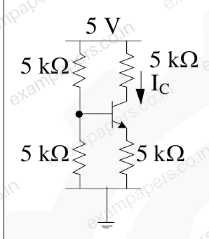
In the circuit shown, the BJT has a
of 100. The base-emitter junction voltage is 0.65 V. The quiescent collector current,
is ______ mA.
Your answerChoose one option.
Log in to check the answer
You can attempt this question now. Sign in to view the answer key, explanations and discussion.Log in to check answerQuestion 34
Open questionINNAT1 markNeeds review
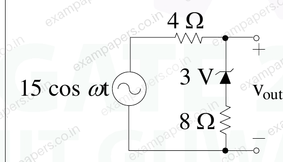
In the circuit below the maximum value of
is _______ V. (rounded off to the nearest integer)
Log in to check the answer
You can attempt this question now. Sign in to view the answer key, explanations and discussion.Log in to check answerQuestion 45
Open questionINMCQ2 marksNeeds review
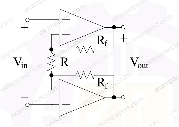
In the circuit shown below, R is 1 kΩ and R_f is 10 kΩ. If V_in is 100 mV and the op-amps have supply voltages of ±15 V, then V_out is ______ V.
Your answerChoose one option.
Log in to check the answer
You can attempt this question now. Sign in to view the answer key, explanations and discussion.Log in to check answerQuestion 46
Open questionINMCQ2 marksNeeds review
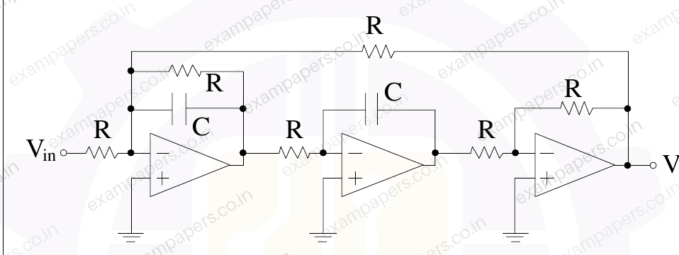
In the following active filter circuit with ideal op-amps, R is 1 kΩ, C is 1 μF, and V_in has an amplitude of 1 V at 1000 rad/s.
The amplitude of V_out is _________ V.
Your answerChoose one option.
Log in to check the answer
You can attempt this question now. Sign in to view the answer key, explanations and discussion.Log in to check answerQuestion 20
Open questionINMCQ1 markNeeds review
For the ideal opamp based circuit shown in the figure, the ratio
is 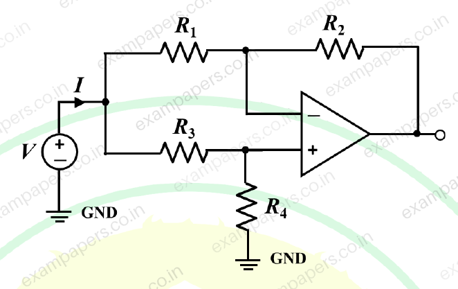
Your answerChoose one option.
Log in to check the answer
You can attempt this question now. Sign in to view the answer key, explanations and discussion.Log in to check answerQuestion 31
Open questionINMSQ1 markNeeds review
The circuits mentioned in the following options are realized using ideal opamp. Among these, the circuit(s) performing non-linear operation on the input signal is/are
Your answerSelect all correct options. You can choose more than one.
Log in to check the answer
You can attempt this question now. Sign in to view the answer key, explanations and discussion.Log in to check answerQuestion 35
Open questionINNAT1 markNeeds review
In the circuit shown, assume that the BJT in the circuit has very high
and
V, and the Zener diode has
V. The current
through the LED is __________ mA (rounded off to two decimal places). 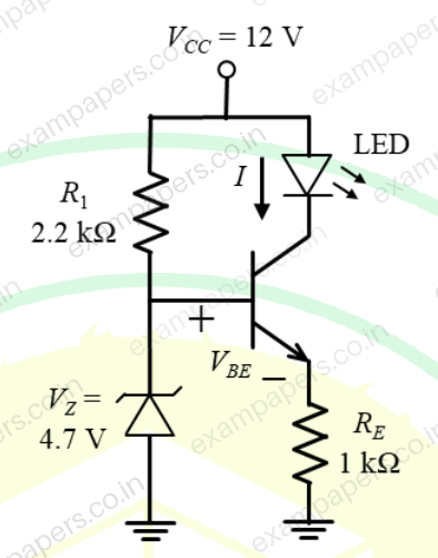
Log in to check the answer
You can attempt this question now. Sign in to view the answer key, explanations and discussion.Log in to check answerQuestion 41
Open questionINMCQ2 marksNeeds review
A chopper amplifier shown in the figure is designed to process a biomedical signal
to generate conditioned output
. The signals
and
are band limited to 50 Hz and 10 Hz, respectively. For the system to operate as a linear amplifier, choose the correct statement from the following options. 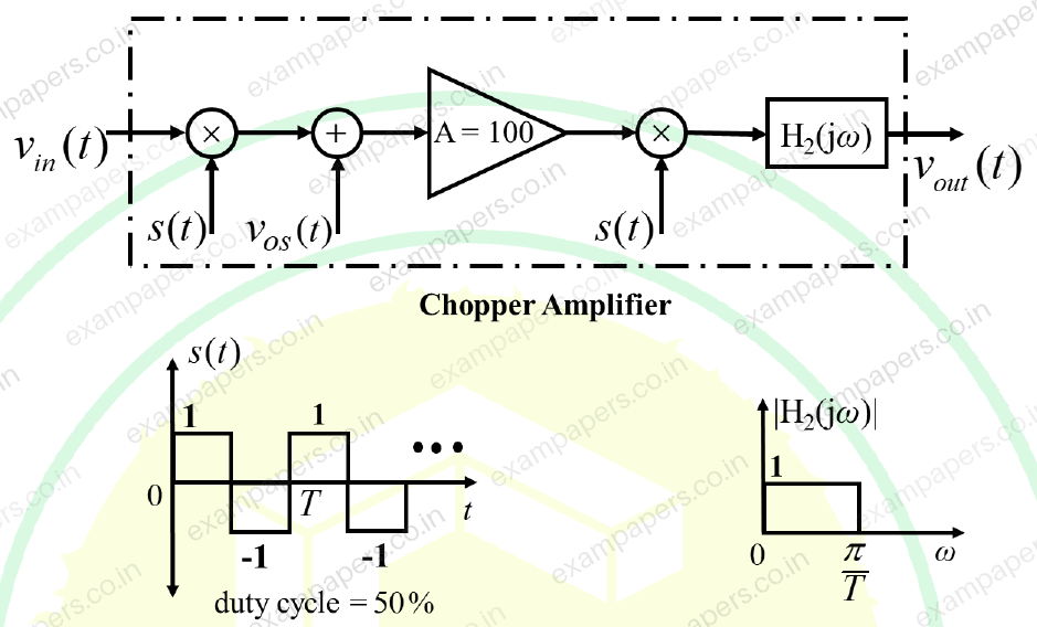
Your answerChoose one option.
Log in to check the answer
You can attempt this question now. Sign in to view the answer key, explanations and discussion.Log in to check answerQuestion 23
Open questionINNAT1 markNeeds review
Consider the circuit shown in the figure.
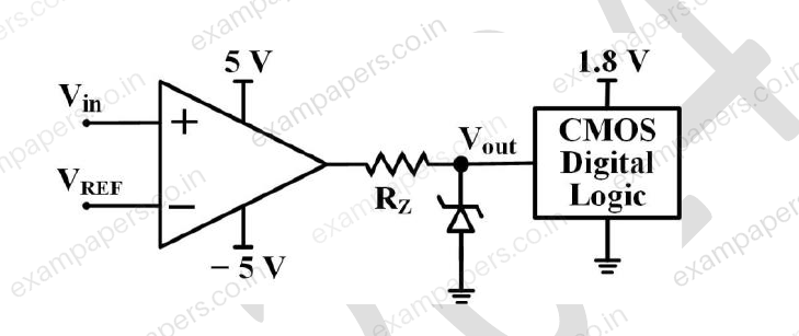
The CMOS digital logic circuit has infinite input impedance. Assume the opamp is ideal. A 1.8 V Zener diode with a minimum Zener current of 2 mA is used. The corresponding maximum value of resistance
is ______ kΩ (rounded off to one decimal place).Log in to check the answer
You can attempt this question now. Sign in to view the answer key, explanations and discussion.Log in to check answer