
Instrumentation Engineering
GATE IN Analog Electronics PYQs
Build your understanding with focused practice from past exam papers.
Questions 51–60 of 65. Imported answers require independent review unless marked reviewed.
Question 22
Open questionINNAT1 markNeeds review
As shown in the figure, temperature
is measured using a K type thermocouple. It has a sensitivity of 40
V/°C. The gain (G) of the ideal instrumentation amplifier is 25. If the output
is 96 mV, then the value of
(in °C) is ___. 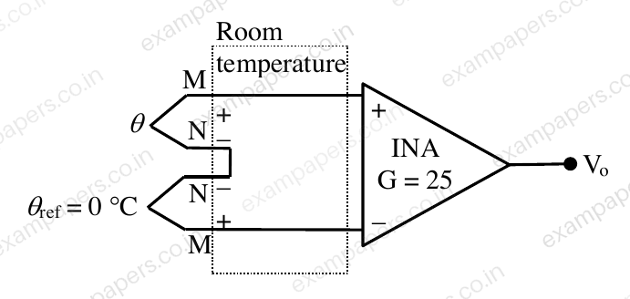
Log in to check the answer
You can attempt this question now. Sign in to view the answer key, explanations and discussion.Log in to check answerQuestion 40
Open questionINNAT2 marksNeeds review
In the given relaxation oscillator, the opamps and the zener diodes are ideal. The frequency (in kHz) of the square wave output
is _____. 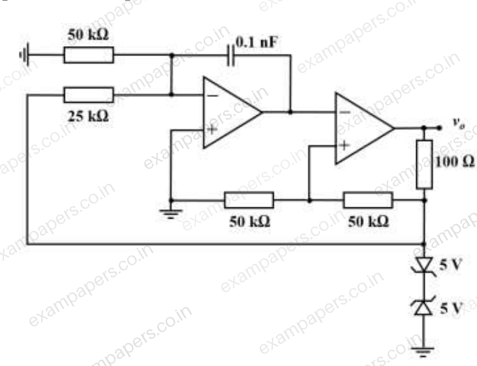
Log in to check the answer
You can attempt this question now. Sign in to view the answer key, explanations and discussion.Log in to check answerQuestion 41
Open questionINNAT2 marksNeeds review
An opamp that is powered from a
V supply is used to build a non-inverting amplifier having a gain of 15. The slew rate of the opamp is
V/s. For a sinusoidal input with amplitude of 0.3 V, the maximum frequency (in kHz) up to which it can be operated without any distortion (up to one decimal place) ____.Log in to check the answer
You can attempt this question now. Sign in to view the answer key, explanations and discussion.Log in to check answerQuestion 42
Open questionINNAT2 marksNeeds review
The circuit given uses ideal opamps. The current I (in
A) drawn from the source
is (up to two decimal places) ____. 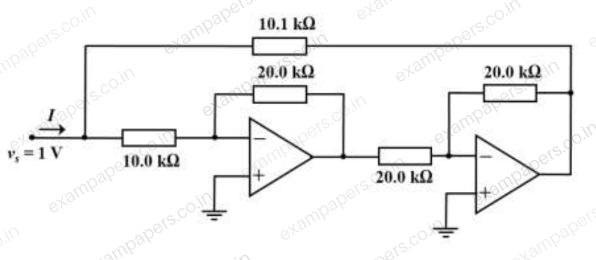
Log in to check the answer
You can attempt this question now. Sign in to view the answer key, explanations and discussion.Log in to check answerQuestion 52
Open questionINNAT2 marksNeeds review
Assuming ideal opamp, the RMS voltage (in mV) in the output Vₒ only due to the 230 V, 50 Hz interference is (up to one decimal place) _____.
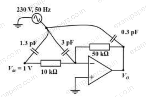
Log in to check the answer
You can attempt this question now. Sign in to view the answer key, explanations and discussion.Log in to check answerQuestion 14
Open questionINNAT1 markNeeds review
The differential amplifier, shown in the figure, has a differential gain of
and common mode gain of
. If
V and
V, then
, in volt (up to one decimal place) is ______.
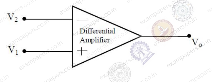
Log in to check the answer
You can attempt this question now. Sign in to view the answer key, explanations and discussion.Log in to check answerQuestion 15
Open questionINMCQ1 markNeeds review
The silicon diode, shown in the figure, has a barrier potential of 0.7 V. There will be no forward current flow through the diode, if
, in volt, is greater than
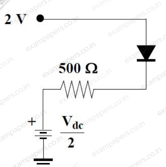
Your answerChoose one option.
Log in to check the answer
You can attempt this question now. Sign in to view the answer key, explanations and discussion.Log in to check answerQuestion 17
Open questionINMCQ1 markNeeds review
The condition for oscillation in a feedback oscillator circuit is that at the frequency of oscillation, initially the loop gain is greater than unity while the total phase shift around the loop in degree is
Your answerChoose one option.
Log in to check the answer
You can attempt this question now. Sign in to view the answer key, explanations and discussion.Log in to check answerQuestion 18
Open questionINMCQ1 markNeeds review
The output
shown in the figure, in volt, is close to
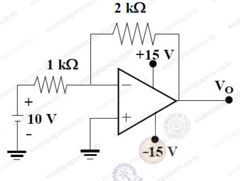
Your answerChoose one option.
Log in to check the answer
You can attempt this question now. Sign in to view the answer key, explanations and discussion.Log in to check answerQuestion 40
Open questionINNAT2 marksNeeds review
Assuming the opamp shown in the figure to be ideal, the frequency at which the magnitude of
will be 95% of the magnitude of
is __________ kHz.
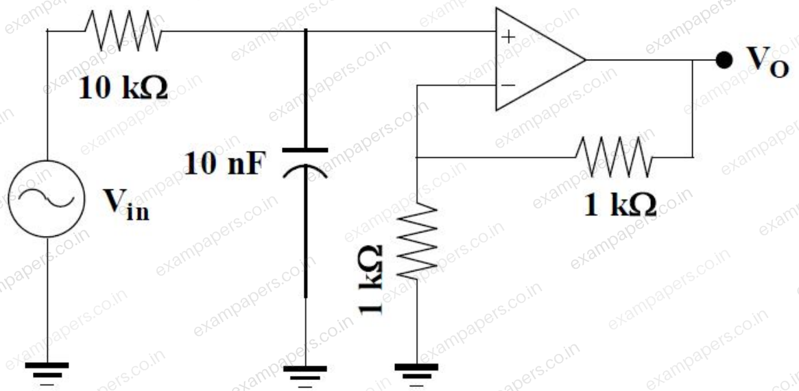
Log in to check the answer
You can attempt this question now. Sign in to view the answer key, explanations and discussion.Log in to check answer