
Instrumentation Engineering
GATE IN concept:mosfet PYQs
Build your understanding with focused practice from past exam papers.
How to practice concept:mosfet
Attempt a question, record the concept and assumptions, then check the available answer. Rework mistakes after revising the relevant concepts. Topic tags can overlap; review the question context.
Questions 1–5 of 5. Imported answers require independent review unless marked reviewed.
Question 44
Open questionINMCQ2 marksNeeds review
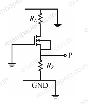
In the small signal circuit shown, the enhancement mode n-channel MOSFET is biased in saturation with transconductance
. If channel length modulation is ignored, the small signal impedance looking into the node P is given by ______
Your answerChoose one option.
Log in to check the answer
You can attempt this question now. Sign in to view the answer key, explanations and discussion.Log in to check answerQuestion 47
Open questionINMCQ2 marksNeeds review
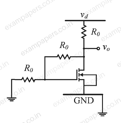
In the small signal circuit shown, the enhancement mode n-channel MOSFET is biased in saturation with a transconductance
. A small signal low-frequency voltage
injected at the supply terminal results in a small signal voltage
at the output. If the channel length modulation of the MOSFET is ignored, the small signal gain
is given by ______
Your answerChoose one option.
Log in to check the answer
You can attempt this question now. Sign in to view the answer key, explanations and discussion.Log in to check answerQuestion 33
Open questionINMCQ2 marksNeeds review
A voltage amplifier is constructed using enhancement mode MOSFETs labeled M1, M2, M3 and M4 in the figure below. M1, M2 and M4 are n-channel MOSFETs and M3 is a p-channel MOSFET. All MOSFETs operate in saturation mode and channel length modulation can be ignored. The low frequency, small signal input and output voltages are
and
respectively and the dc power supply voltage is
. All n-channel MOSFETs have identical transconductance
while the p-channel MOSFET has transconductance
. The expressions for the low frequency small signal voltage gain
is 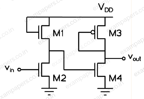
Your answerChoose one option.
Log in to check the answer
You can attempt this question now. Sign in to view the answer key, explanations and discussion.Log in to check answerQuestion 50
Open questionINNAT2 marksNeeds review
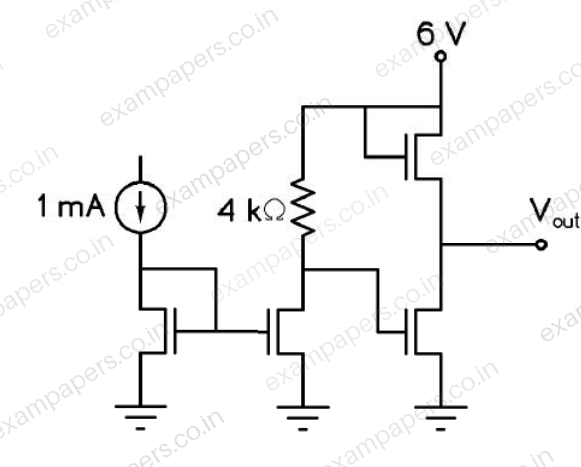
In the circuit shown below, all transistors are n-channel enhancement mode MOSFETs. They are identical and are biased to operate in saturation mode. Ignoring channel length modulation, the output voltage
is ______ V.
Log in to check the answer
You can attempt this question now. Sign in to view the answer key, explanations and discussion.Log in to check answerQuestion 41
Open questionINNAT2 marksNeeds review
In the circuit, shown in the figure, the MOSFET is operating in the saturation zone. The characteristics of the MOSFET is given by
, where
is in V. If
, then the value of
in k
is __________.
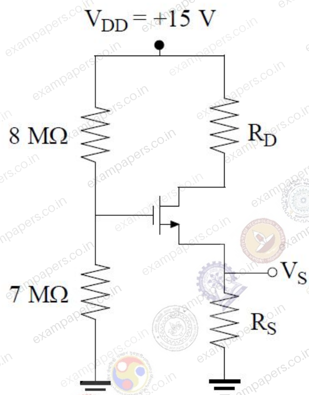
Log in to check the answer
You can attempt this question now. Sign in to view the answer key, explanations and discussion.Log in to check answer