
Instrumentation Engineering
GATE IN concept:voltage PYQs
Build your understanding with focused practice from past exam papers.
How to practice concept:voltage
Attempt a question, record the concept and assumptions, then check the available answer. Rework mistakes after revising the relevant concepts. Topic tags can overlap; review the question context.
Questions 1–10 of 16. Imported answers require independent review unless marked reviewed.
Question 29
Open questionINMSQ1 markNeeds review
In a linear element, the measured current is 100 mA ± 2.5% and the measured voltage is 5 V ± 5%. Which of the following options show(s) the consumed power?
Your answerSelect all correct options. You can choose more than one.
Log in to check the answer
You can attempt this question now. Sign in to view the answer key, explanations and discussion.Log in to check answerQuestion 21
Open questionINMCQ1 markNeeds review
In a single-phase AC circuit, the power consumed by load resistance
for an excitation
is measured using a wattmeter. The same wattmeter is connected in two different topologies, Topology-A and Topology-B, as shown in the figure. Different branch currents and voltage drops are also marked in the figure. Among the following options, the condition that ensures low error in the wattmeter reading for both the topologies is 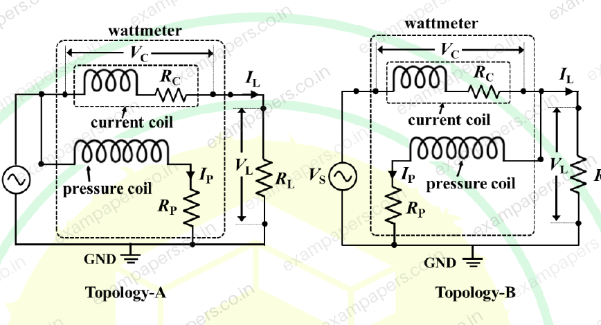
Your answerChoose one option.
Log in to check the answer
You can attempt this question now. Sign in to view the answer key, explanations and discussion.Log in to check answerQuestion 23
Open questionINMCQ1 markNeeds review
A 3½ digit digital voltmeter has a specified accuracy of
. If it is used to measure 10 V DC voltage, the error in the measurement would beNote: Accuracy of the digital voltmeter is expressed as ± (% of reading + digit).
Your answerChoose one option.
Log in to check the answer
You can attempt this question now. Sign in to view the answer key, explanations and discussion.Log in to check answerQuestion 26
Open questionINMCQ1 markNeeds review
An oscilloscope has an input resistance of 1 M
. A 10X passive attenuating probe is connected to it to increase the input voltage range as well as the effective input resistance. The effective input resistance, in M
, seen into the probe tip isYour answerChoose one option.
Log in to check the answer
You can attempt this question now. Sign in to view the answer key, explanations and discussion.Log in to check answerQuestion 47
Open questionINMCQ2 marksNeeds review
In the figure shown, assume
is the phase angle between the load current and the load voltage
is the phase angle by which pressure coil current lags the pressure coil voltage of the wattmeter
is the phase angle between currents in the pressure coil and the current coil of the wattmeter
is the phase angle of the voltage transformer
is the phase angle of the current transformerWhen the load has a lagging phase angle of
, which one of the following options is correct? 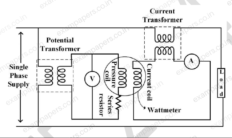
Your answerChoose one option.
Log in to check the answer
You can attempt this question now. Sign in to view the answer key, explanations and discussion.Log in to check answerQuestion 34
Open questionINNAT1 markNeeds review
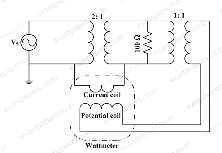
The full-scale range of the wattmeter shown in the circuit is 100 W. The turns ratio of the individual transformers are indicated in the figure. The RMS value of the ac source voltage
is 200 V. The wattmeter reading will be ______ W (rounded off to the nearest integer).
Log in to check the answer
You can attempt this question now. Sign in to view the answer key, explanations and discussion.Log in to check answerQuestion 61
Open questionINNAT2 marksNeeds review
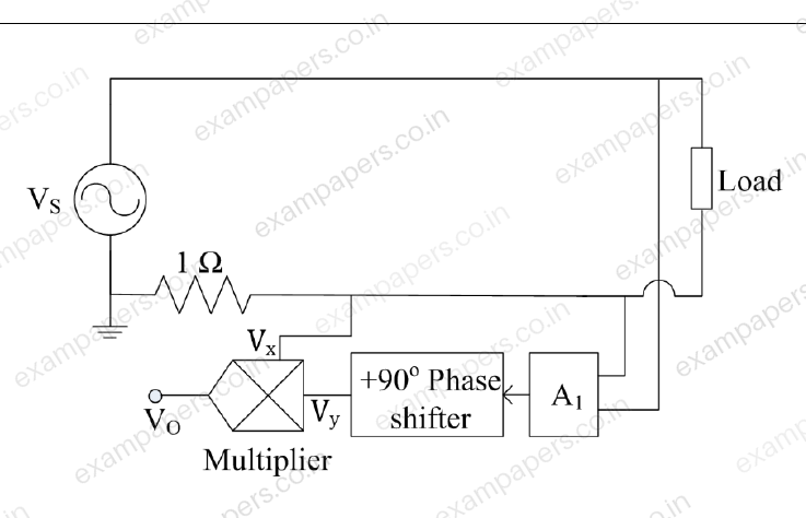
In the diagram shown, the frequency of the sinusoidal source voltage
is 50 Hz. The load voltage is 230 V (RMS), and the load impedance is
. The value of attenuator
. The multiplier output voltage
, where
and
are the inputs. The magnitude of the average value of the multiplier output
is __________ V (rounded off to one decimal place).
Log in to check the answer
You can attempt this question now. Sign in to view the answer key, explanations and discussion.Log in to check answerQuestion 63
Open questionINNAT2 marksNeeds review
The bridge shown is balanced when
,
,
F, and
. The 2 kHz sine-wave generator supplies a voltage of 10 V
. The value of
(in millihenry) is ______ (round off to two decimal places) 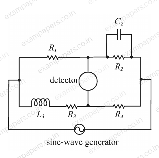
Log in to check the answer
You can attempt this question now. Sign in to view the answer key, explanations and discussion.Log in to check answerQuestion 65
Open questionINNAT2 marksNeeds review
In the Wheatstone bridge circuit shown,
and
. The switch is initially open and the voltage between the points C and D is
. Upon closing the switch at
, the resistance in the arm AD changes by an amount
, and the voltage between C and D changes by
. The sensitivity of the bridge (in volt/kilohm), defined as
, is ________ (round off to two decimal places) 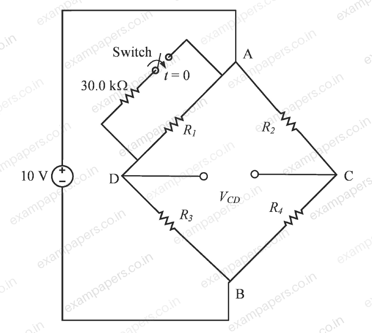
Log in to check the answer
You can attempt this question now. Sign in to view the answer key, explanations and discussion.Log in to check answerQuestion 5
Open questionINMCQ1 markNeeds review
In an ac main, the rms voltage
, rms current
and power
are measured as:
,
and
(errors are with respect to readings). The percentage error in calculating the power factor using these readings isYour answerChoose one option.
Log in to check the answer
You can attempt this question now. Sign in to view the answer key, explanations and discussion.Log in to check answer