
Instrumentation Engineering
GATE IN concept:zener-diode PYQs
Build your understanding with focused practice from past exam papers.
How to practice concept:zener-diode
Attempt a question, record the concept and assumptions, then check the available answer. Rework mistakes after revising the relevant concepts. Topic tags can overlap; review the question context.
Questions 1–7 of 7. Imported answers require independent review unless marked reviewed.
Question 35
Open questionINNAT1 markNeeds review
In the circuit shown, assume that the BJT in the circuit has very high
and
V, and the Zener diode has
V. The current
through the LED is __________ mA (rounded off to two decimal places). 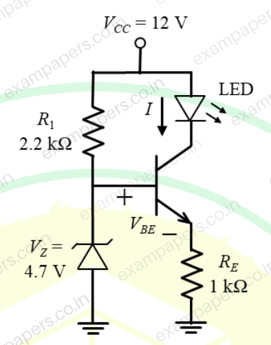
Log in to check the answer
You can attempt this question now. Sign in to view the answer key, explanations and discussion.Log in to check answerQuestion 23
Open questionINNAT1 markNeeds review
Consider the circuit shown in the figure.
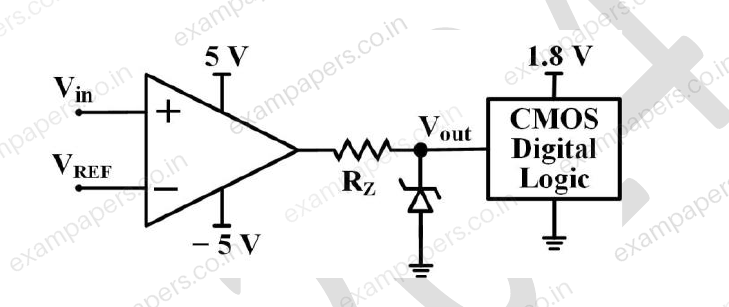
The CMOS digital logic circuit has infinite input impedance. Assume the opamp is ideal. A 1.8 V Zener diode with a minimum Zener current of 2 mA is used. The corresponding maximum value of resistance
is ______ kΩ (rounded off to one decimal place).Log in to check the answer
You can attempt this question now. Sign in to view the answer key, explanations and discussion.Log in to check answerQuestion 31
Open questionINNAT1 markNeeds review
A Zener diode is used as a 4 V voltage regulator in the circuit shown. Given that the diode requires a minimum current of 4 mA for voltage regulation, the maximum current (in milliamperes) permitted to flow through the load
is ______ (round off to one decimal place)
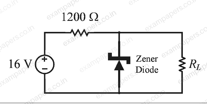
Log in to check the answer
You can attempt this question now. Sign in to view the answer key, explanations and discussion.Log in to check answerQuestion 7
Open questionINMCQ1 markNeeds review
If the diodes in the circuit shown are ideal and the breakdown voltage
of the Zener diode is 5 V, the power dissipated in the 100
resistor (in watts) is ____. 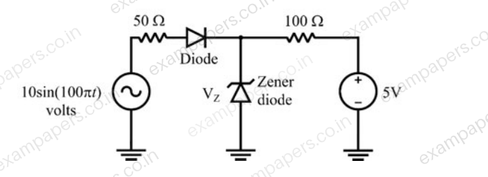
Your answerChoose one option.
Log in to check the answer
You can attempt this question now. Sign in to view the answer key, explanations and discussion.Log in to check answerQuestion 11
Open questionINMCQ1 markNeeds review
The correct biasing conditions for typical operation of light emitting diodes, photodiodes, Zener diodes are, respectively
Your answerChoose one option.
Log in to check the answer
You can attempt this question now. Sign in to view the answer key, explanations and discussion.Log in to check answerQuestion 40
Open questionINNAT2 marksNeeds review
In the given relaxation oscillator, the opamps and the zener diodes are ideal. The frequency (in kHz) of the square wave output
is _____. 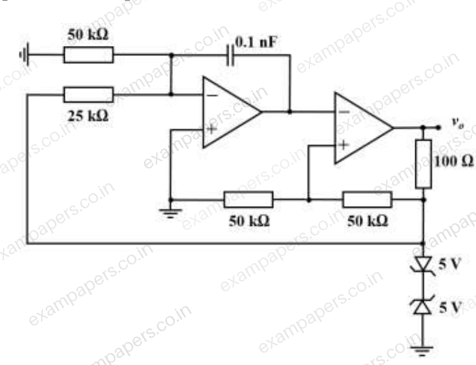
Log in to check the answer
You can attempt this question now. Sign in to view the answer key, explanations and discussion.Log in to check answerQuestion 44
Open questionINNAT2 marksNeeds review
The circuit of a Schmitt trigger is shown in the figure.
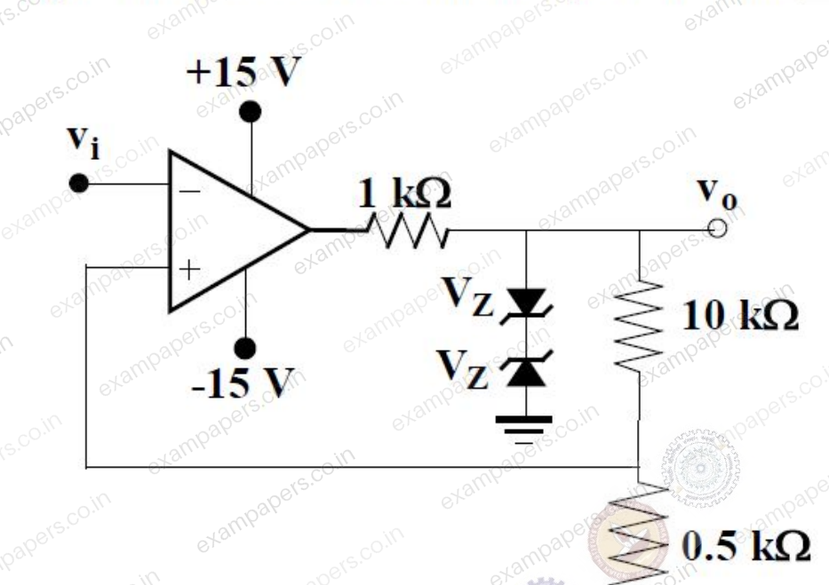
The zener-diode combination maintains the output between
. The width of the hysteresis band is __________ V.Log in to check the answer
You can attempt this question now. Sign in to view the answer key, explanations and discussion.Log in to check answer