
Instrumentation Engineering
GATE IN Digital Electronics PYQs
Build your understanding with focused practice from past exam papers.
How to practice Digital Electronics
Attempt a question, record the concept and assumptions, then check the available answer. Rework mistakes after revising the relevant concepts. Topic tags can overlap; review the question context.
Questions 1–10 of 57. Imported answers require independent review unless marked reviewed.
Question 23
Open questionINMCQ1 markNeeds review
The maximum signal to quantization noise ratio (SNR) for a 16-bit analog-to-digital converter is approximate ______ dB.
Your answerChoose one option.
Log in to check the answer
You can attempt this question now. Sign in to view the answer key, explanations and discussion.Log in to check answerQuestion 35
Open questionINNAT1 markNeeds review
The minimum number of comparators required in a 6-bit flash analog-to-digital converter is _______. (answer in integer)
Log in to check the answer
You can attempt this question now. Sign in to view the answer key, explanations and discussion.Log in to check answerQuestion 47
Open questionINMCQ2 marksNeeds review
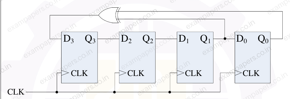
The initial state of Q₃Q₂Q₁Q₀ in the digital circuit shown below is 1011.
The new value of Q₃Q₂Q₁Q₀ after two rising edges of the clock (CLK) will be _____.
Your answerChoose one option.
Log in to check the answer
You can attempt this question now. Sign in to view the answer key, explanations and discussion.Log in to check answerQuestion 55
Open questionINMSQ2 marksNeeds review
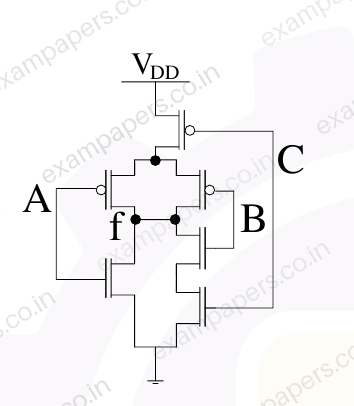
Which of the following functions represent(s) the output of the CMOS logic-gate shown in the circuit below?
Your answerSelect all correct options. You can choose more than one.
Log in to check the answer
You can attempt this question now. Sign in to view the answer key, explanations and discussion.Log in to check answerQuestion 56
Open questionINMSQ2 marksNeeds review
A 16-bit processor has 16-bit wide instructions and a few internal registers. Every 16-bit instruction is encoded in a fixed format with one operation code of 7 bits and up to three operands. The operand can be an internal register and each operand is encoded by 3 bits. All the internal registers can be specified in an instruction using three bits.
The correct statement(s) for this processor is/are _____.
Your answerSelect all correct options. You can choose more than one.
Log in to check the answer
You can attempt this question now. Sign in to view the answer key, explanations and discussion.Log in to check answerQuestion 17
Open questionINMCQ1 markNeeds review
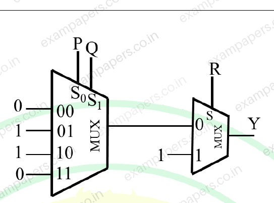
The minimized expression of the Boolean function Y(P, Q, R) implemented by the multiplexer (MUX) circuit shown in the figure is
Your answerChoose one option.
Log in to check the answer
You can attempt this question now. Sign in to view the answer key, explanations and discussion.Log in to check answerQuestion 18
Open questionINMCQ1 markNeeds review
The 4-bit signed 2’s complement form of
isYour answerChoose one option.
Log in to check the answer
You can attempt this question now. Sign in to view the answer key, explanations and discussion.Log in to check answerQuestion 29
Open questionINMCQ1 markNeeds review
A Boolean function X is given as
. The reduced form of
isYour answerChoose one option.
Log in to check the answer
You can attempt this question now. Sign in to view the answer key, explanations and discussion.Log in to check answerQuestion 34
Open questionINNAT1 markNeeds review
A dual-slope ADC has a fixed integration time of 100 ms. The reference voltage of the ADC is −5 V. The time taken by the ADC to measure an input voltage of 1.25 V is __________ ms (rounded to the nearest integer).
Log in to check the answer
You can attempt this question now. Sign in to view the answer key, explanations and discussion.Log in to check answerQuestion 40
Open questionINMCQ2 marksNeeds review
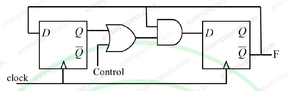
The clock frequency of the digital circuit shown in the figure is 12 MHz. The frequencies of the output (F) corresponding to Control = 0 and Control = 1, respectively, are
Your answerChoose one option.
Log in to check the answer
You can attempt this question now. Sign in to view the answer key, explanations and discussion.Log in to check answer