
Instrumentation Engineering
GATE IN discipline:electrical-electronics-and-instrumentation PYQs
Build your understanding with focused practice from past exam papers.
Questions 251–260 of 650. Imported answers require independent review unless marked reviewed.
Question 56
Open questionINNAT2 marksNeeds review
The figure below shows a feedback amplifier constructed using an nMOS transistor. Assume that
mA/V
, threshold voltage
V and W/L = 2. The bias voltage at the drain terminal is 4 V. The capacitors
offer zero impedance at the signal frequency. The ratio
is ____________(rounded off to two decimal places). 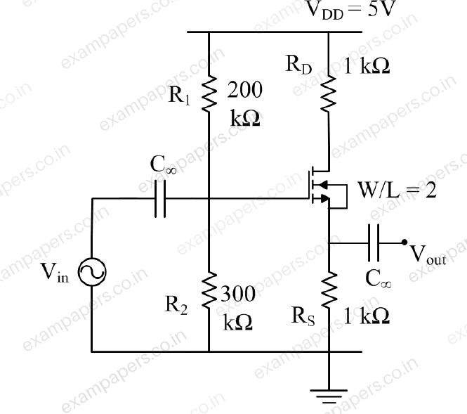
Log in to check the answer
You can attempt this question now. Sign in to view the answer key, explanations and discussion.Log in to check answerQuestion 57
Open questionINNAT2 marksNeeds review
Consider the real-valued function
, where
. The minimum value attained by
is ______ (rounded off to one decimal place).Log in to check the answer
You can attempt this question now. Sign in to view the answer key, explanations and discussion.Log in to check answerQuestion 58
Open questionINNAT2 marksNeeds review
A short-circuit test is conducted on a single-phase transformer by shorting its secondary. The frequency of input voltage is 1 kHz. The corresponding wattmeter reading, primary current and primary voltage are 8 W, 2 A and 6 V respectively. Assume that the no-load losses and the no-load currents are negligible, and the core has linear magnetic characteristics. Keeping the secondary short, the primary is connected to a 2 V (RMS), 1 kHz sinusoidal source in series with a
mF capacitor. The primary current (RMS) will be _____ A (rounded off to two decimal places).Log in to check the answer
You can attempt this question now. Sign in to view the answer key, explanations and discussion.Log in to check answerQuestion 59
Open questionINNAT2 marksNeeds review
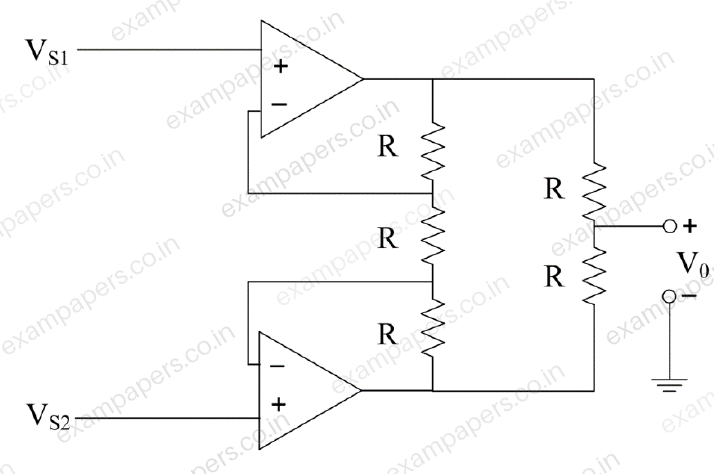
The opamps in the circuit are ideal. The input signals are
V and
V. The average value of the voltage
is _____ V (rounded off to two decimal places).
Log in to check the answer
You can attempt this question now. Sign in to view the answer key, explanations and discussion.Log in to check answerQuestion 60
Open questionINNAT2 marksNeeds review
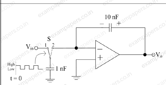
In the circuit shown, the input voltage
mV. The switch and the opamp are ideal. At time
, the initial charge stored in the 10 nF capacitor is 1 nC, with the polarity as indicated in the figure. The switch S is controlled using a 1 kHz square-wave voltage signal
as shown. Whenever
is ‘High’, S is in position ‘1’ and when
is ‘Low’, S is in position ‘2’.
At
ms, the magnitude of the voltage
will be ______ mV (rounded off to the nearest integer).Log in to check the answer
You can attempt this question now. Sign in to view the answer key, explanations and discussion.Log in to check answerQuestion 61
Open questionINNAT2 marksNeeds review
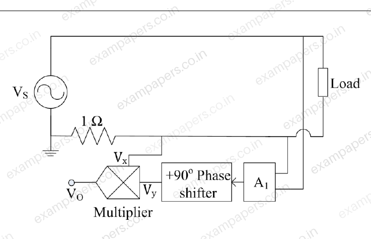
In the diagram shown, the frequency of the sinusoidal source voltage
is 50 Hz. The load voltage is 230 V (RMS), and the load impedance is
. The value of attenuator
. The multiplier output voltage
, where
and
are the inputs. The magnitude of the average value of the multiplier output
is __________ V (rounded off to one decimal place).
Log in to check the answer
You can attempt this question now. Sign in to view the answer key, explanations and discussion.Log in to check answerQuestion 62
Open questionINNAT2 marksNeeds review
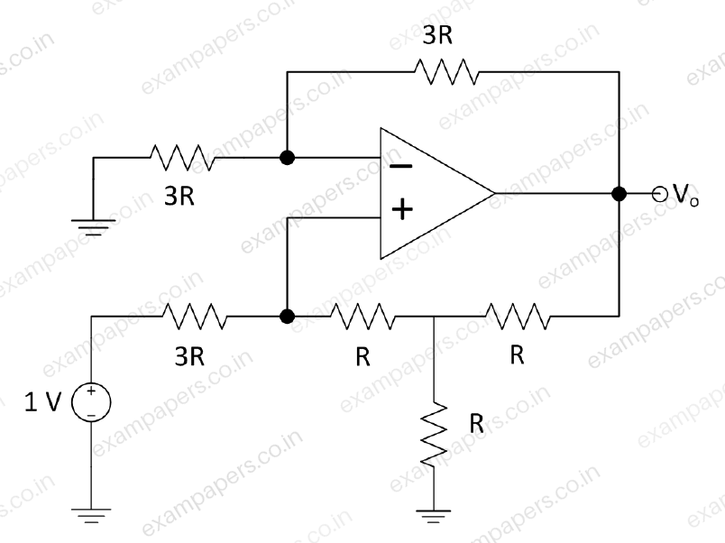
In the circuit shown, assuming an ideal opamp, the value of the output voltage
____ V (rounded off to one decimal place).
Log in to check the answer
You can attempt this question now. Sign in to view the answer key, explanations and discussion.Log in to check answerQuestion 63
Open questionINNAT2 marksNeeds review
The rank of the matrix
given below is one. The ratio
is ______ (rounded off to the nearest integer).
Log in to check the answer
You can attempt this question now. Sign in to view the answer key, explanations and discussion.Log in to check answerQuestion 64
Open questionINNAT2 marksNeeds review
A 1.999 V True RMS 3-1/2 digit multimeter has an accuracy of ±0.1 % of reading ±2 digits. It is used to measure 100 A (RMS) current flowing through a line using a 100:5 ratio, Class-1 current transformer with a burden of 0.1 Ω ±0.5 %. The worst-case absolute error in the multimeter output is ________ V (rounded off to three decimal places).
Log in to check the answer
You can attempt this question now. Sign in to view the answer key, explanations and discussion.Log in to check answerQuestion 65
Open questionINNAT2 marksNeeds review
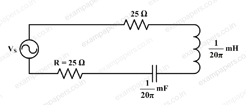
The voltage source
V has an internal resistance of 50 Ω. The RMS value of the current through R is ______mA (rounded off to one decimal place).
Log in to check the answer
You can attempt this question now. Sign in to view the answer key, explanations and discussion.Log in to check answer