
Instrumentation Engineering
GATE IN Electrical Circuits PYQs
Build your understanding with focused practice from past exam papers.
How to practice Electrical Circuits
Attempt a question, record the concept and assumptions, then check the available answer. Rework mistakes after revising the relevant concepts. Topic tags can overlap; review the question context.
Questions 1–10 of 44. Imported answers require independent review unless marked reviewed.
Question 40
Open questionINMCQ2 marksNeeds review
In the circuit shown below, the value of the output voltage
is ____ V. 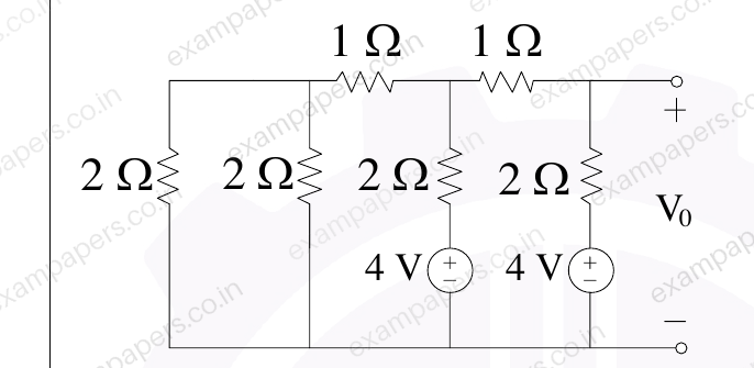
Your answerChoose one option.
Log in to check the answer
You can attempt this question now. Sign in to view the answer key, explanations and discussion.Log in to check answerQuestion 24
Open questionINMCQ1 markNeeds review
The circuit shown in Figure (a) can be represented using its equivalent T-model as shown in Figure (b). The values of the inductances
,
, and
in the equivalent T-model are 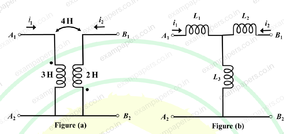
Your answerChoose one option.
Log in to check the answer
You can attempt this question now. Sign in to view the answer key, explanations and discussion.Log in to check answerQuestion 45
Open questionINMCQ2 marksNeeds review
The bridge circuit, shown in Figure (a), can be equivalently represented using the circuit shown in Figure (b). The values of R₁, R₂, and V_C in the equivalent circuit are
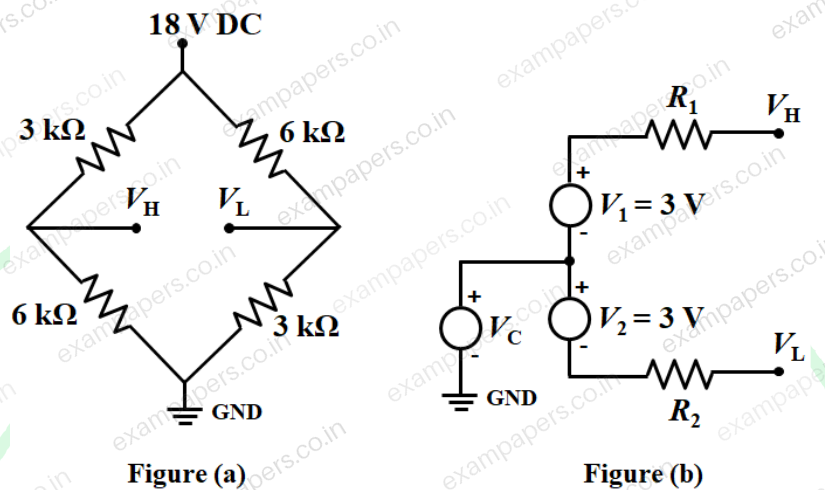
Your answerChoose one option.
Log in to check the answer
You can attempt this question now. Sign in to view the answer key, explanations and discussion.Log in to check answerQuestion 61
Open questionINNAT2 marksNeeds review
In the circuit shown, the galvanometer (G) has an internal resistance of 100 Ω. The galvanometer current
is ______ μA (rounded off to the nearest integer).
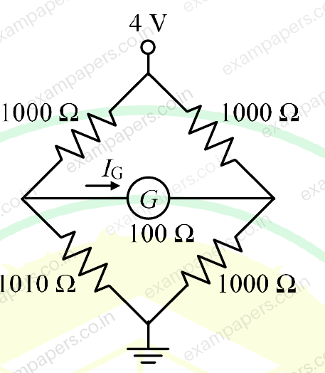
Log in to check the answer
You can attempt this question now. Sign in to view the answer key, explanations and discussion.Log in to check answerQuestion 63
Open questionINNAT2 marksNeeds review
In the circuit shown, the switch is opened at
s. The current
at
ms is ____________ mA (rounded off to two decimal places). 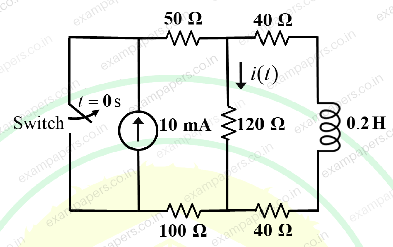
Log in to check the answer
You can attempt this question now. Sign in to view the answer key, explanations and discussion.Log in to check answerQuestion 64
Open questionINNAT2 marksNeeds review
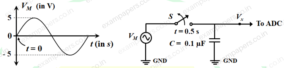
A signal
V is applied to the circuit consisting of a switch S and capacitor C = 0.1
F, as shown in the figure. The output
of the circuit is fed to an ADC having an input impedance consisting of a 10 M
resistance in parallel with a 0.1
F capacitor. If S is opened at
s, the value of
at
s will be ______ V (rounded off to two decimal places).Note: Assume all components are ideal.
Log in to check the answer
You can attempt this question now. Sign in to view the answer key, explanations and discussion.Log in to check answerQuestion 65
Open questionINNAT2 marksNeeds review
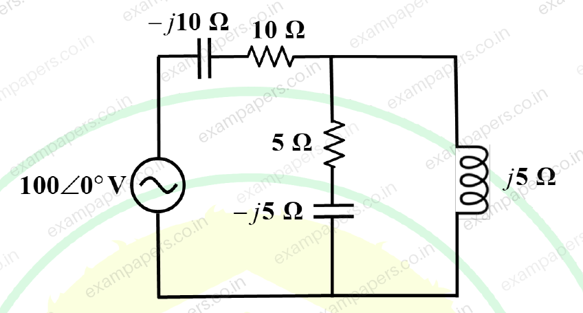
For the circuit shown in the figure, the active power supplied by the source is ______ W (rounded off to one decimal place).
Log in to check the answer
You can attempt this question now. Sign in to view the answer key, explanations and discussion.Log in to check answerQuestion 30
Open questionINNAT1 markNeeds review
The voltage applied and the current drawn by a circuit are
The average power absorbed by the circuit is ________ W (rounded off to nearest integer).Log in to check the answer
You can attempt this question now. Sign in to view the answer key, explanations and discussion.Log in to check answerQuestion 31
Open questionINNAT1 markNeeds review
The current
drawn by a circuit is given as
The root-mean-square value of
is ________ A (rounded off to one decimal place).Log in to check the answer
You can attempt this question now. Sign in to view the answer key, explanations and discussion.Log in to check answerQuestion 31
Open questionINNAT1 markNeeds review
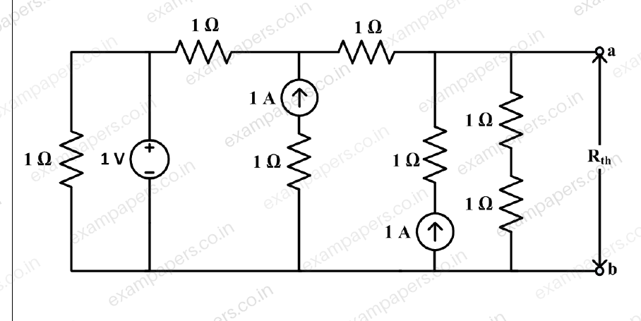
In the circuit given, the Thevenin equivalent resistance Rₜₕ across the terminals ‘a’ and ‘b’ is __________Ω (rounded off to one decimal place).
Log in to check the answer
You can attempt this question now. Sign in to view the answer key, explanations and discussion.Log in to check answer