
Instrumentation Engineering
GATE IN Electrical Circuits PYQs
Build your understanding with focused practice from past exam papers.
Questions 31–40 of 44. Imported answers require independent review unless marked reviewed.
Question 17
Open questionINNAT1 markNeeds review
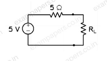
In the circuit shown below, maximum power is transferred to the load resistance
, when
______ Ω.
Log in to check the answer
You can attempt this question now. Sign in to view the answer key, explanations and discussion.Log in to check answerQuestion 18
Open questionINNAT1 markNeeds review
Consider a circuit comprising only resistors with constant resistance and ideal independent DC voltage sources. If all the resistances are scaled down by a factor 10, and all source voltages are scaled up by a factor 10, the power dissipated in the circuit scales up by a factor of ______ .
Log in to check the answer
You can attempt this question now. Sign in to view the answer key, explanations and discussion.Log in to check answerQuestion 45
Open questionINNAT2 marksNeeds review
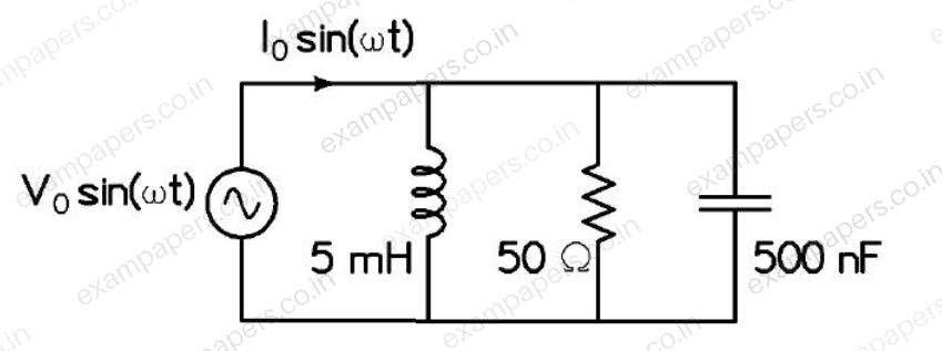
In the circuit shown below, the angular frequency
at which the current is in phase with the voltage is ______ rad/s.
Log in to check the answer
You can attempt this question now. Sign in to view the answer key, explanations and discussion.Log in to check answerQuestion 6
Open questionINMCQ1 markNeeds review
A series R-C circuit is excited by a
V sinusoidal ac voltage source. The locus diagram of the phasor current
A, when C is varied, while keeping R fixed, isYour answerChoose one option.
Log in to check the answer
You can attempt this question now. Sign in to view the answer key, explanations and discussion.Log in to check answerQuestion 7
Open questionINMCQ1 markNeeds review
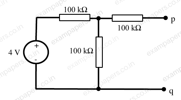
Thevenin equivalent circuit representation across terminals p-q of the circuit shown in the figure is a
Your answerChoose one option.
Log in to check the answer
You can attempt this question now. Sign in to view the answer key, explanations and discussion.Log in to check answerQuestion 8
Open questionINNAT1 markNeeds review
A coil having an impedance of
is connected in parallel to a variable capacitor as shown in figure. Keeping the excitation frequency unchanged, the value of the capacitor is changed so that parallel resonance occurs. The impedance across terminals p-q at resonance (in
) is _____. 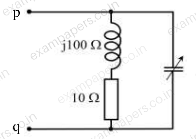
Log in to check the answer
You can attempt this question now. Sign in to view the answer key, explanations and discussion.Log in to check answerQuestion 30
Open questionINNAT2 marksNeeds review
In the given circuit, superposition is applied. When
is set to 0 V, the current
is −6 A. When
is set to 0 V, the current
is +6 A. Current
(in A) when both sources are applied will be (up to two decimal places) ____. 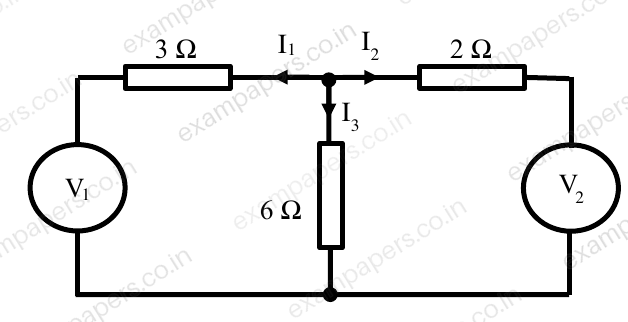
Log in to check the answer
You can attempt this question now. Sign in to view the answer key, explanations and discussion.Log in to check answerQuestion 31
Open questionINNAT2 marksNeeds review
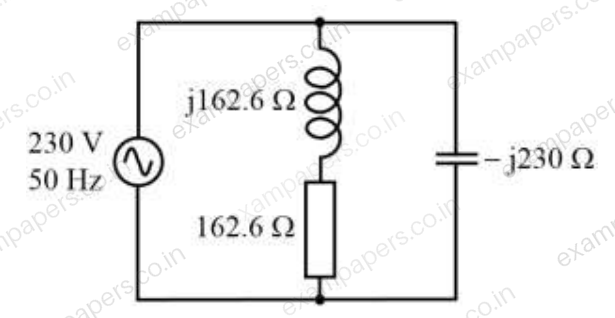
In the figure, an RLC load is supplied by a 230 V, 50 Hz single phase source. The magnitude of the reactive power (in VAr) supplied by the source is ________.
Log in to check the answer
You can attempt this question now. Sign in to view the answer key, explanations and discussion.Log in to check answerQuestion 32
Open questionINMCQ2 marksNeeds review
In the given circuit, the mesh currents
,
and
are 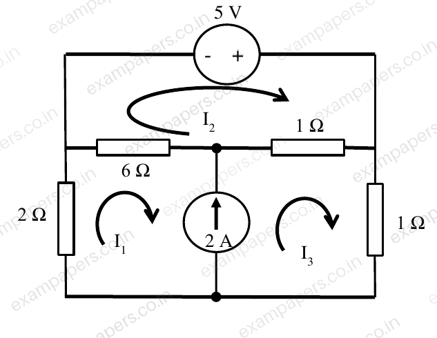
Your answerChoose one option.
Log in to check the answer
You can attempt this question now. Sign in to view the answer key, explanations and discussion.Log in to check answerQuestion 6
Open questionINNAT1 markNeeds review
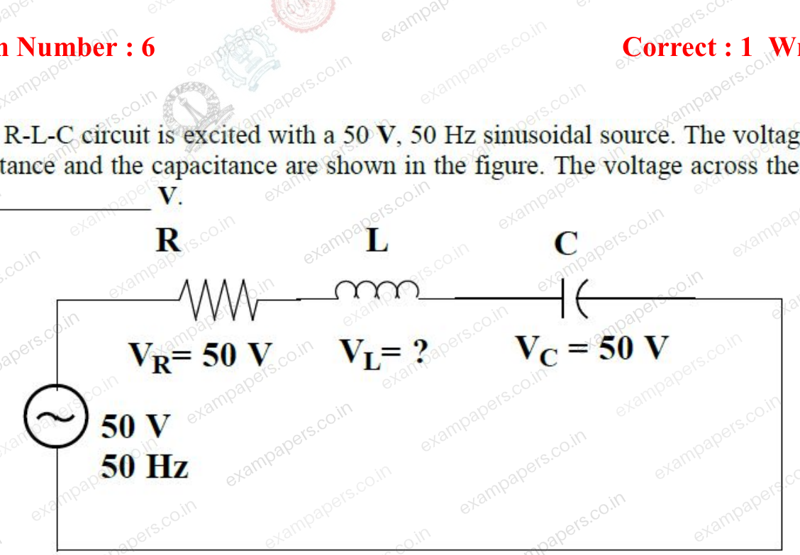
A series R-L-C circuit is excited with a 50 V, 50 Hz sinusoidal source. The voltages across the resistance and the capacitance are shown in the figure. The voltage across the inductor (
) is ______ V.
Log in to check the answer
You can attempt this question now. Sign in to view the answer key, explanations and discussion.Log in to check answer