
Instrumentation Engineering
GATE IN exam:gate PYQs
Build your understanding with focused practice from past exam papers.
Questions 121–130 of 650. Imported answers require independent review unless marked reviewed.
Question 56
Open questionINNAT2 marksNeeds review
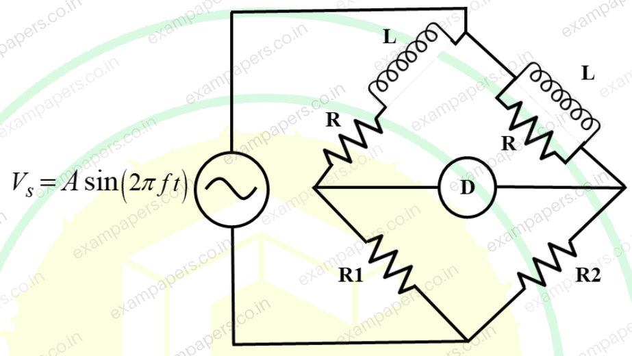
Consider an AC bridge shown in the figure with
,
,
,
, and a detector
. The source voltage is
. At the bridge balance condition, the frequency of the excitation source
is ________ kHz (rounded off to two decimal places).
Log in to check the answer
You can attempt this question now. Sign in to view the answer key, explanations and discussion.Log in to check answerQuestion 57
Open questionINNAT2 marksNeeds review
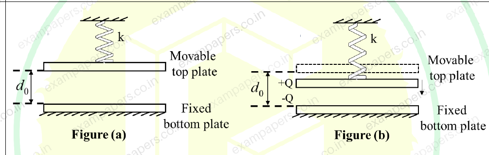
An air filled parallel plate electrostatic actuator is shown in the figure. The area of each capacitor plate is 100 μm × 100 μm. The distance between the plates
μm when both the capacitor charge and spring restoring force are zero as shown in Figure (a). A linear spring of constant k = 0.01 N/m is connected to the movable plate. When charge is supplied to the capacitor using a current source, the top plate moves as shown in Figure (b). The magnitude of minimum charge (Q) required to momentarily close the gap between the plates is ______×
C (rounded off to two decimal places).Note: Assume a full range of motion is possible for the top plate and there is no fringe capacitance. The permittivity of free space is
F/m and relative permittivity of air (
) is 1.
Log in to check the answer
You can attempt this question now. Sign in to view the answer key, explanations and discussion.Log in to check answerQuestion 58
Open questionINNAT2 marksNeeds review
The resistance of a thermistor is measured to be 2.25 kΩ at 30 °C and 1.17 kΩ at 60 °C. Its material constant
is __________ K (rounded off to two decimal places).Log in to check the answer
You can attempt this question now. Sign in to view the answer key, explanations and discussion.Log in to check answerQuestion 59
Open questionINNAT2 marksNeeds review
A feedback control system is shown in the figure.
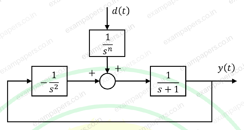
The maximum allowable value of
such that the output
, due to any step disturbance signal
, becomes zero at steady-state, is ________ (in integer).Log in to check the answer
You can attempt this question now. Sign in to view the answer key, explanations and discussion.Log in to check answerQuestion 60
Open questionINNAT2 marksNeeds review
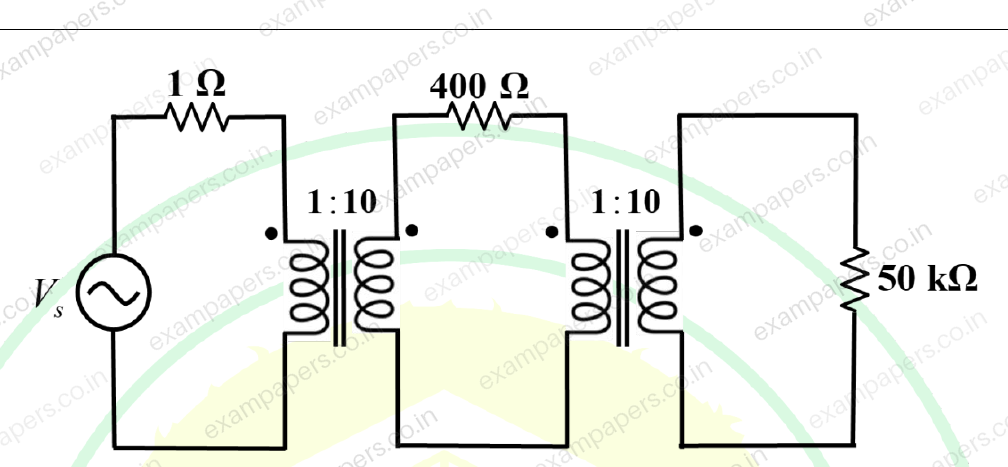
The circuit given in the figure is driven by a voltage source
V. The system is operating at a frequency of 50 Hz. The transformers are assumed to be ideal. The average power dissipated, in W, in the 50 kΩ resistance is ______ (rounded off to two decimal places).
Log in to check the answer
You can attempt this question now. Sign in to view the answer key, explanations and discussion.Log in to check answerQuestion 61
Open questionINNAT2 marksNeeds review
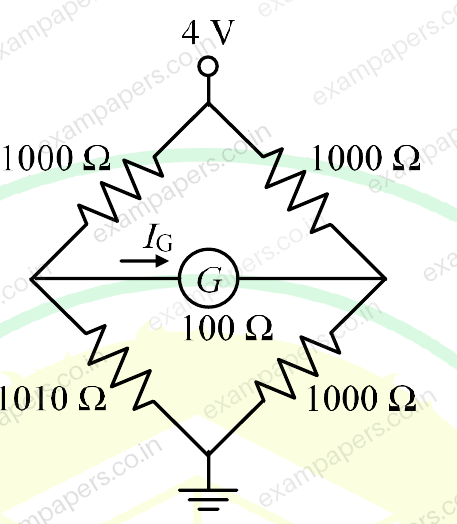
In the circuit shown, the galvanometer (G) has an internal resistance of 100 Ω. The galvanometer current
is ______ μA (rounded off to the nearest integer).
Log in to check the answer
You can attempt this question now. Sign in to view the answer key, explanations and discussion.Log in to check answerQuestion 62
Open questionINNAT2 marksNeeds review
A series RLC circuit resonates at 750 rad/s for inductance L = 20 mH and resistance R = 10
. The uncertainties in the measurement of L and R are 0.8 mH and 0.3
, respectively. The percentage uncertainty in the measurement of quality factor is ______% (rounded off to one decimal place).Log in to check the answer
You can attempt this question now. Sign in to view the answer key, explanations and discussion.Log in to check answerQuestion 63
Open questionINNAT2 marksNeeds review
In the circuit shown, the switch is opened at
s. The current
at
ms is ____________ mA (rounded off to two decimal places). 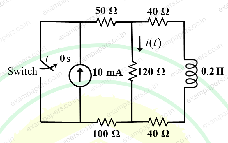
Log in to check the answer
You can attempt this question now. Sign in to view the answer key, explanations and discussion.Log in to check answerQuestion 64
Open questionINNAT2 marksNeeds review
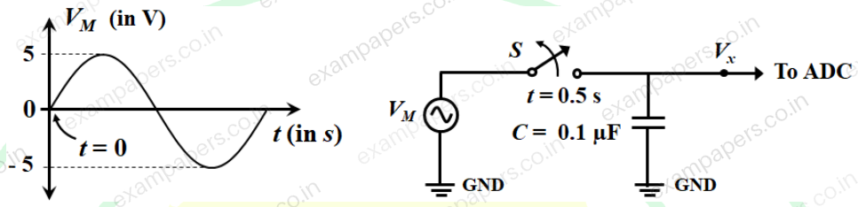
A signal
V is applied to the circuit consisting of a switch S and capacitor C = 0.1
F, as shown in the figure. The output
of the circuit is fed to an ADC having an input impedance consisting of a 10 M
resistance in parallel with a 0.1
F capacitor. If S is opened at
s, the value of
at
s will be ______ V (rounded off to two decimal places).Note: Assume all components are ideal.
Log in to check the answer
You can attempt this question now. Sign in to view the answer key, explanations and discussion.Log in to check answerQuestion 65
Open questionINNAT2 marksNeeds review
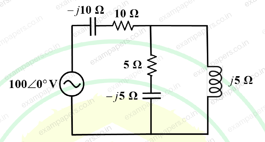
For the circuit shown in the figure, the active power supplied by the source is ______ W (rounded off to one decimal place).
Log in to check the answer
You can attempt this question now. Sign in to view the answer key, explanations and discussion.Log in to check answer