
Instrumentation Engineering
GATE IN exam:gate PYQs
Build your understanding with focused practice from past exam papers.
Questions 621–630 of 650. Imported answers require independent review unless marked reviewed.
Question 36
Open questionINNAT2 marksNeeds review
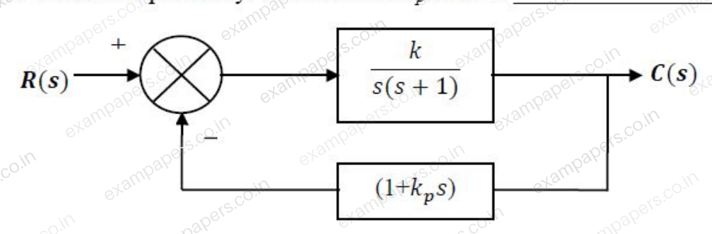
The block diagram of a closed-loop control system is shown in the figure. The values of
and
are such that the system has a damping ratio of 0.8 and an undamped natural frequency
of
respectively. The value of
will be __________.
Log in to check the answer
You can attempt this question now. Sign in to view the answer key, explanations and discussion.Log in to check answerQuestion 37
Open questionINNAT2 marksNeeds review
The loop transfer function of a closed-loop system is given by
. The breakaway point of the root-locus will be __________.Log in to check the answer
You can attempt this question now. Sign in to view the answer key, explanations and discussion.Log in to check answerQuestion 38
Open questionINMCQ2 marksNeeds review
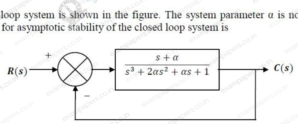
A closed-loop system is shown in the figure. The system parameter
is not known. The condition for asymptotic stability of the closed loop system is
Your answerChoose one option.
Log in to check the answer
You can attempt this question now. Sign in to view the answer key, explanations and discussion.Log in to check answerQuestion 39
Open questionINMCQ2 marksNeeds review
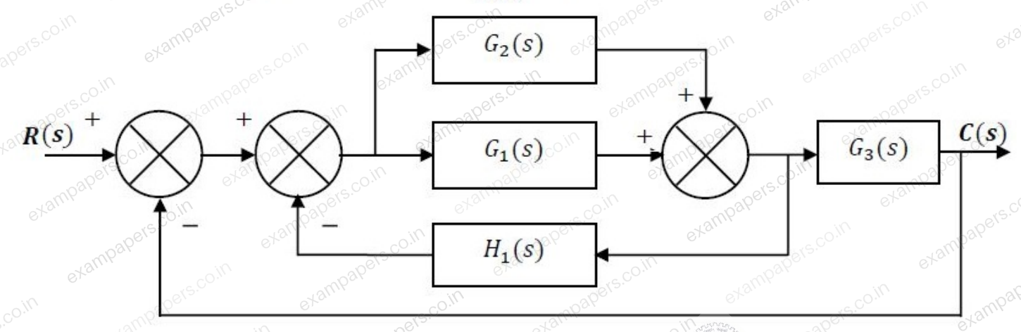
The overall closed loop transfer function
, represented in the figure, will be
Your answerChoose one option.
Log in to check the answer
You can attempt this question now. Sign in to view the answer key, explanations and discussion.Log in to check answerQuestion 40
Open questionINNAT2 marksNeeds review
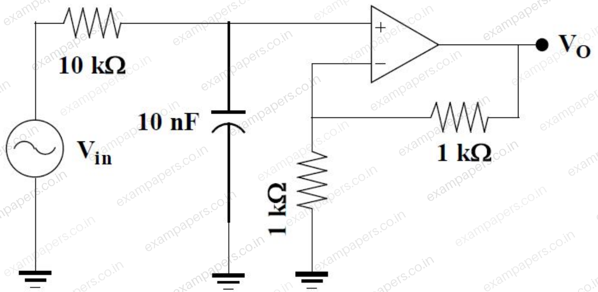
Assuming the opamp shown in the figure to be ideal, the frequency at which the magnitude of
will be 95% of the magnitude of
is __________ kHz.
Log in to check the answer
You can attempt this question now. Sign in to view the answer key, explanations and discussion.Log in to check answerQuestion 41
Open questionINNAT2 marksNeeds review
In the circuit, shown in the figure, the MOSFET is operating in the saturation zone. The characteristics of the MOSFET is given by
, where
is in V. If
, then the value of
in k
is __________.
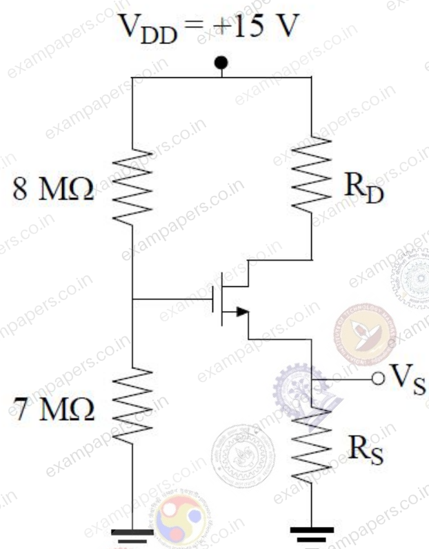
Log in to check the answer
You can attempt this question now. Sign in to view the answer key, explanations and discussion.Log in to check answerQuestion 42
Open questionINNAT2 marksNeeds review
The two-input voltage multiplier, shown in the figure, has a scaling factor of 1 and produces voltage output. If
and
, the value of
in volt is __________.
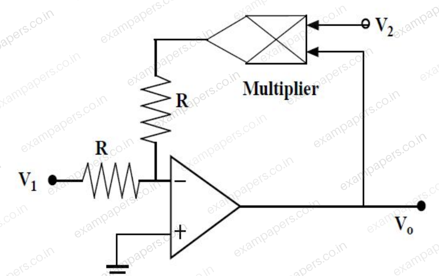
Log in to check the answer
You can attempt this question now. Sign in to view the answer key, explanations and discussion.Log in to check answerQuestion 43
Open questionINMCQ2 marksNeeds review
The two inputs A and B are connected to an R-S latch via two AND gates as shown in the figure.
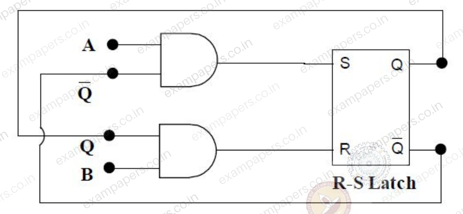
If A = 1 and B = 0, the output
isYour answerChoose one option.
Log in to check the answer
You can attempt this question now. Sign in to view the answer key, explanations and discussion.Log in to check answerQuestion 44
Open questionINNAT2 marksNeeds review
The circuit of a Schmitt trigger is shown in the figure.
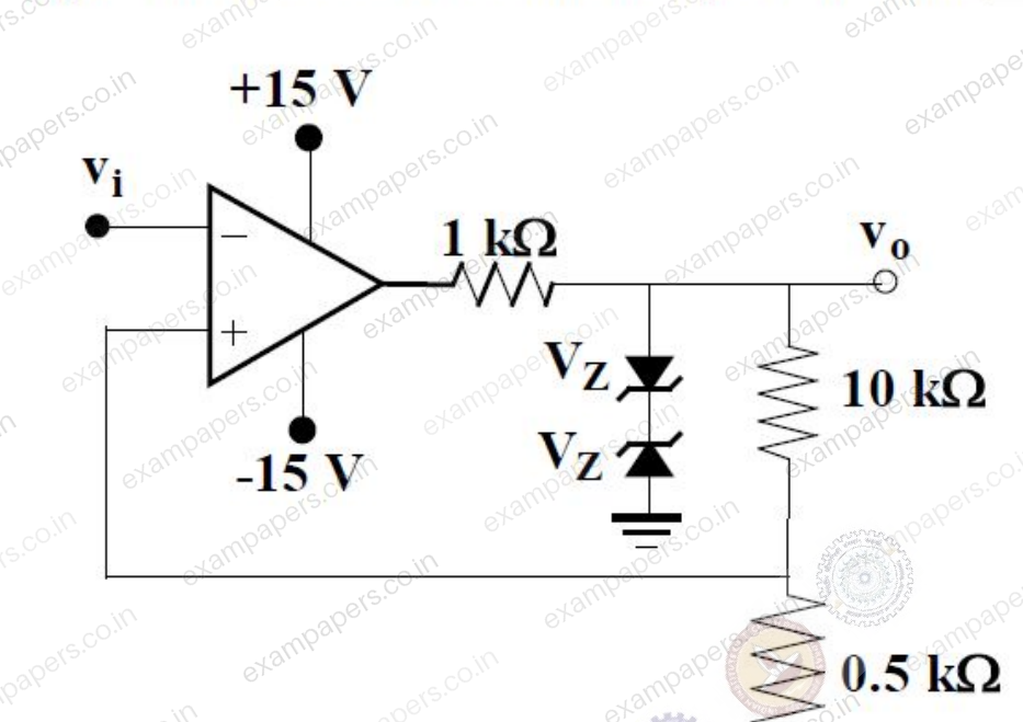
The zener-diode combination maintains the output between
. The width of the hysteresis band is __________ V.Log in to check the answer
You can attempt this question now. Sign in to view the answer key, explanations and discussion.Log in to check answerQuestion 45
Open questionINNAT2 marksNeeds review
When the voltage across a battery is measured using a d.c. potentiometer, the reading shows 1.08 V. But when the same voltage is measured using a Permanent Magnet Moving Coil (PMMC) voltmeter, the voltmeter reading shows 0.99 V. If the resistance of the voltmeter is 1100
, the internal resistance of the battery, in
, is __________.Log in to check the answer
You can attempt this question now. Sign in to view the answer key, explanations and discussion.Log in to check answer