
Instrumentation Engineering
GATE IN format:nat PYQs
Build your understanding with focused practice from past exam papers.
Questions 171–180 of 270. Imported answers require independent review unless marked reviewed.
Question 36
Open questionINNAT2 marksNeeds review
The loop transfer function of a negative feedback system is given by
, where
. The value of
at the breakaway point of the root locus for the above system (rounded off to one decimal place) is ____Log in to check the answer
You can attempt this question now. Sign in to view the answer key, explanations and discussion.Log in to check answerQuestion 37
Open questionINNAT2 marksNeeds review
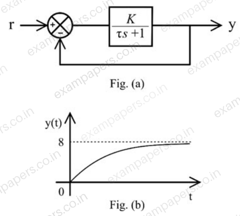
The system shown in Fig. (a) has a time response
to an input
as shown in Fig. (b),
being the unit step input. Both
are positive. The gain
of the system is ____
Log in to check the answer
You can attempt this question now. Sign in to view the answer key, explanations and discussion.Log in to check answerQuestion 38
Open questionINNAT2 marksNeeds review
Assuming that the opamp used in the circuit shown is ideal, the reading of the 1 Hz bandwidth, permanent magnet moving coil (PMMC) type voltmeter (in volts) is ____

Log in to check the answer
You can attempt this question now. Sign in to view the answer key, explanations and discussion.Log in to check answerQuestion 39
Open questionINNAT2 marksNeeds review
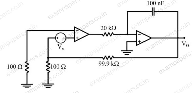
If the opamps in the circuit shown are ideal and
mV, the steady state value of
(in volts, rounded off to two decimal places) is ____
Log in to check the answer
You can attempt this question now. Sign in to view the answer key, explanations and discussion.Log in to check answerQuestion 40
Open questionINNAT2 marksNeeds review
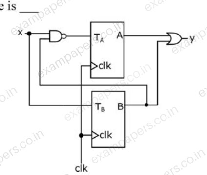
Two T-flip flops are interconnected as shown in the figure. The present state of the flip flops are: A = 1, B = 1. The input x is given as 1, 0, 1 in the next three clock cycles. The decimal equivalent of
with A being the MSB and B being the LSB, after the 3rd clock cycle is ____
Log in to check the answer
You can attempt this question now. Sign in to view the answer key, explanations and discussion.Log in to check answerQuestion 41
Open questionINNAT2 marksNeeds review
The address lines A9 … A2 of a 10 bit, 1.023 V full-scale digital to analog converter (DAC) is connected to the data lines D7 to D0 of an 8-bit microprocessor, with A1 and A0 of the DAC grounded. Now, D7 … D0 is changed from 1010 1010 to 1010 1011. The corresponding change in the output of the DAC (in mV, rounded off to one decimal place) is ____
Log in to check the answer
You can attempt this question now. Sign in to view the answer key, explanations and discussion.Log in to check answerQuestion 42
Open questionINNAT2 marksNeeds review
The real power drawn by a balanced load connected to a 400 V, 50 Hz, balanced, symmetrical 3-phase, 3-wire, RYB sequence mains is measured using the two-wattmeter method. Wattmeter W1 is connected in the R line and wattmeter W2 is connected in the B line. The line current is measured as
A. If the wattmeter W1 reads zero, the reading on W2 (in watts) is ____Log in to check the answer
You can attempt this question now. Sign in to view the answer key, explanations and discussion.Log in to check answerQuestion 43
Open questionINNAT2 marksNeeds review
A 6½ digit timer-counter is set in the ‘time period’ mode of operation and the range is set as ‘ns’. For an input signal, the timer-counter displays 100000. With the same input signal, the timer-counter is changed to ‘frequency’ mode of operation and the range is set as ‘Hz’. The display will show the number ____
Log in to check the answer
You can attempt this question now. Sign in to view the answer key, explanations and discussion.Log in to check answerQuestion 44
Open questionINNAT2 marksNeeds review
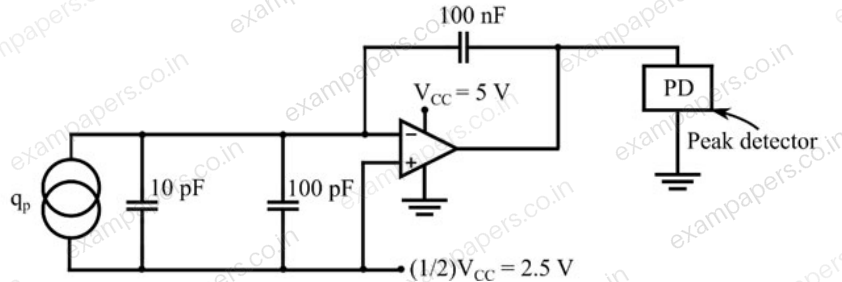
The circuit shown uses ideal opamp powered from a supply
V. If the charge
generated by the piezoelectric sensor is of the form
μC, the peak detector output after 10 cycles of
(in volts, rounded off to one decimal place) is ____
Log in to check the answer
You can attempt this question now. Sign in to view the answer key, explanations and discussion.Log in to check answerQuestion 45
Open questionINNAT2 marksNeeds review
A metallic strain gauge of resistance
with a gauge factor of 2 is bonded to a structure made of a metal with modulus of elasticity of 200 GN/m
. The value of
is 1 kΩ when no stress is applied.
is a part of a quarter bridge with three identical fixed resistors of 1 kΩ each. The bridge is excited from a DC voltage of 4 V. The structure is subjected to a stress of 100 MN/m
. Magnitude of the output of the bridge (in mV, rounded off to two decimal places) is ____Log in to check the answer
You can attempt this question now. Sign in to view the answer key, explanations and discussion.Log in to check answer