
Instrumentation Engineering
GATE IN format:nat PYQs
Build your understanding with focused practice from past exam papers.
Questions 211–220 of 270. Imported answers require independent review unless marked reviewed.
Question 53
Open questionINNAT2 marksNeeds review
In a microprocessor with a 16 bit address bus, the most significant address lines A15 to A12 are used to select a 4096 word memory unit, while lines A0 to A11 are used to address a particular word in the memory unit. If the 3 least significant lines of the address bus A0 to A2 are short-circuited to ground, the addressable number of words in the memory unit is ______.
Log in to check the answer
You can attempt this question now. Sign in to view the answer key, explanations and discussion.Log in to check answerQuestion 54
Open questionINNAT2 marksNeeds review
A signal
has a bandwidth
about a carrier frequency of
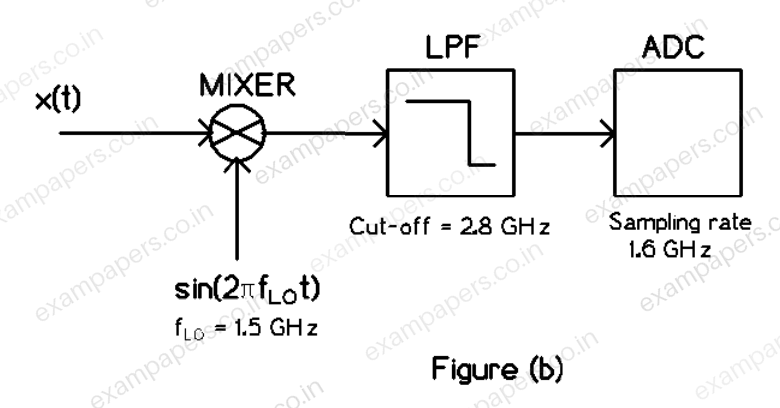
GHz as shown in Figure (a) below. In order to demodulate this signal, it is first mixed (multiplied) with a local oscillator of frequency
GHz, and then passed through an ideal low-pass filter (LPF) with a cut-off frequency of 2.8 GHz. The output of the LPF is sent to a digitizer ADC with a sampling rate of 1.6 GHz as shown in Figure (b) below. The maximum value of
so that the signal
can be reconstructed from its samples according to the Nyquist sampling theorem is ______ MHz. 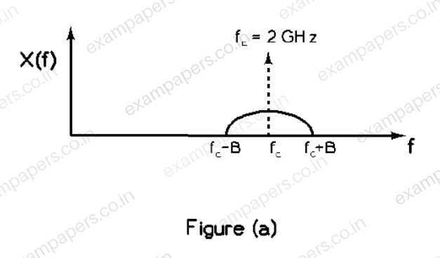
Log in to check the answer
You can attempt this question now. Sign in to view the answer key, explanations and discussion.Log in to check answerQuestion 55
Open questionINNAT2 marksNeeds review
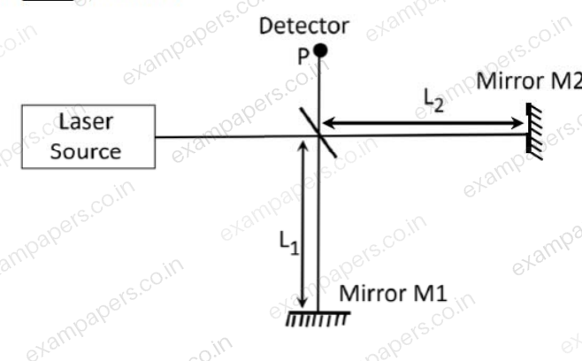
Consider a Michelson interferometer as shown in the figure below. When the wavelength of the laser light source is switched from 400 nanometer to 500 nanometer, it is observed that the intensity measured at the output port P goes from a minimum to a maximum. This observation is possible when the smallest path difference between the two arms of the interferometer is ____ nanometer.
Log in to check the answer
You can attempt this question now. Sign in to view the answer key, explanations and discussion.Log in to check answerQuestion 4
Open questionINNAT1 markNeeds review
Consider two functions
and
, where
is real. The smallest value of
for which
is _____.Log in to check the answer
You can attempt this question now. Sign in to view the answer key, explanations and discussion.Log in to check answerQuestion 8
Open questionINNAT1 markNeeds review
A coil having an impedance of
is connected in parallel to a variable capacitor as shown in figure. Keeping the excitation frequency unchanged, the value of the capacitor is changed so that parallel resonance occurs. The impedance across terminals p-q at resonance (in
) is _____. 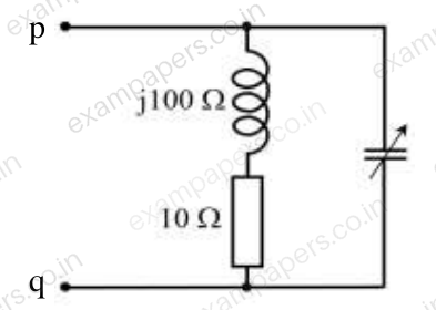
Log in to check the answer
You can attempt this question now. Sign in to view the answer key, explanations and discussion.Log in to check answerQuestion 12
Open questionINNAT1 markNeeds review
An input
is applied to the system
. The corresponding steady state output is
, where the phase
(in degrees), when restricted to
, is ____ .Log in to check the answer
You can attempt this question now. Sign in to view the answer key, explanations and discussion.Log in to check answerQuestion 14
Open questionINNAT1 markNeeds review
Consider the transfer function
. The phase margin of
in degrees is _____.Log in to check the answer
You can attempt this question now. Sign in to view the answer key, explanations and discussion.Log in to check answerQuestion 15
Open questionINNAT1 markNeeds review
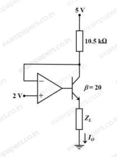
In the given circuit, assume that the opamp is ideal and the transistor has a
of 20. The current
(in
A) flowing through the load
is _____.
Log in to check the answer
You can attempt this question now. Sign in to view the answer key, explanations and discussion.Log in to check answerQuestion 16
Open questionINNAT1 markNeeds review
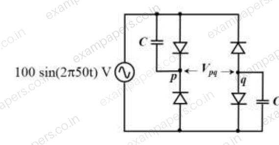
The diodes given in the circuit are ideal. At
ms,
(in Volts) is _____.
Log in to check the answer
You can attempt this question now. Sign in to view the answer key, explanations and discussion.Log in to check answerQuestion 17
Open questionINNAT1 markNeeds review
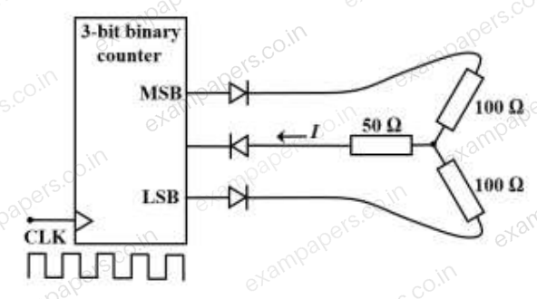
For the 3-bit binary counter shown in the figure, the output increments at every positive transition in the clock (CLK). Assume ideal diodes and the start state of the counter as 000. If output high is 1 V and output low is 0 V, the current I (in mA) flowing through the 50 Ω resistor during the 5ᵗʰ clock cycle is (up to one decimal place) ______.
Log in to check the answer
You can attempt this question now. Sign in to view the answer key, explanations and discussion.Log in to check answer