
Instrumentation Engineering
GATE IN Measurements PYQs
Build your understanding with focused practice from past exam papers.
Questions 11–20 of 59. Imported answers require independent review unless marked reviewed.
Question 53
Open questionINNAT2 marksNeeds review
A metallic strain-gage (SG) with resistance
is connected as shown in the figure, where
represent the lead wire resistances. The SG has a gauge factor of 2 and nominal resistance
of
. When the SG is subjected to a tensile strain of
, the resulting change in
is
. The
value is measured as
. The
and
are the equivalent resistances measured between the terminals 1 and 2, and terminals 2 and 3, respectively.If
, and
, the measured value of tensile strain is ___
(rounded off to two decimal places). 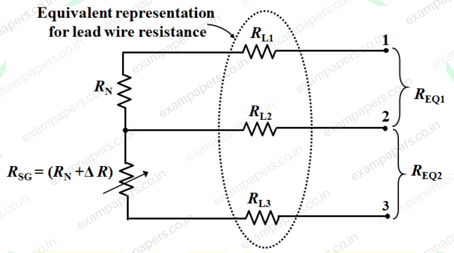
Log in to check the answer
You can attempt this question now. Sign in to view the answer key, explanations and discussion.Log in to check answerQuestion 62
Open questionINNAT2 marksNeeds review
A series RLC circuit resonates at 750 rad/s for inductance L = 20 mH and resistance R = 10
. The uncertainties in the measurement of L and R are 0.8 mH and 0.3
, respectively. The percentage uncertainty in the measurement of quality factor is ______% (rounded off to one decimal place).Log in to check the answer
You can attempt this question now. Sign in to view the answer key, explanations and discussion.Log in to check answerQuestion 28
Open questionINNAT1 markNeeds review
The resistance of a 20 kΩ resistor is measured six consecutive times using an LCR meter. The first five readings are 19 kΩ, 18 kΩ, 23 kΩ, 21 kΩ and 17 kΩ. If the mean of the measurements and the true value are equal, the last reading is ________ kΩ (rounded off to nearest integer).
Log in to check the answer
You can attempt this question now. Sign in to view the answer key, explanations and discussion.Log in to check answerQuestion 37
Open questionINMCQ2 marksNeeds review
The measured values from a flow instrument, whose range is between 0 and 2 flow units, are shown in the histogram. The systematic error (bias) and the maximum error (in flow units), respectively are
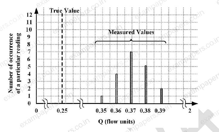
Your answerChoose one option.
Log in to check the answer
You can attempt this question now. Sign in to view the answer key, explanations and discussion.Log in to check answerQuestion 39
Open questionINMCQ2 marksNeeds review
In the bridge circuit shown in the figure, under balanced condition, the values of R and C respectively, are
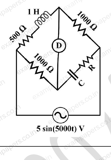
Your answerChoose one option.
Log in to check the answer
You can attempt this question now. Sign in to view the answer key, explanations and discussion.Log in to check answerQuestion 47
Open questionINMCQ2 marksNeeds review
In the figure shown, assume
is the phase angle between the load current and the load voltage
is the phase angle by which pressure coil current lags the pressure coil voltage of the wattmeter
is the phase angle between currents in the pressure coil and the current coil of the wattmeter
is the phase angle of the voltage transformer
is the phase angle of the current transformerWhen the load has a lagging phase angle of
, which one of the following options is correct? 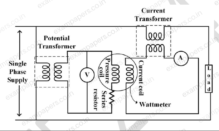
Your answerChoose one option.
Log in to check the answer
You can attempt this question now. Sign in to view the answer key, explanations and discussion.Log in to check answerQuestion 50
Open questionINNAT2 marksNeeds review
The readings recorded from a 20-psig pressure gauge are given in the Table. The regression line obtained for the data is
. The regression coefficient of determination,
______ (rounded off to three decimal places). | 1 | 2 | 3 | 4 | 5 |
|---|---|---|---|---|---|
(psig) | 10.3 | 10.5 | 10.4 | 10.5 | 10.5 |
Log in to check the answer
You can attempt this question now. Sign in to view the answer key, explanations and discussion.Log in to check answerQuestion 54
Open questionINNAT2 marksNeeds review
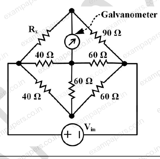
Consider the figure shown. For zero deflection in the galvanometer, the required value of resistor R_x is ____ Ω (rounded off to nearest integer).
Log in to check the answer
You can attempt this question now. Sign in to view the answer key, explanations and discussion.Log in to check answerQuestion 60
Open questionINNAT2 marksNeeds review
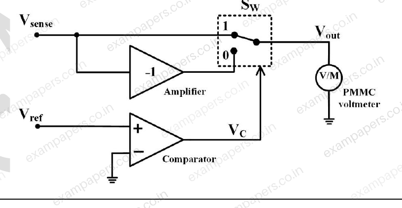
In the figure shown, S_W is a switch whose position changes from 1 to 0 when V_C changes from logic HIGH to LOW and vice versa. The bandwidth of the permanent magnet moving coil (PMC) type voltmeter is 1 Hz. If V_sense = 2 sin(4000πt) V and V_ref = 4 sin(2000πt) V, the voltmeter reading is ______ V (rounded off to nearest integer).
Note: Assume all components are ideal.
Log in to check the answer
You can attempt this question now. Sign in to view the answer key, explanations and discussion.Log in to check answerQuestion 15
Open questionINMCQ1 markNeeds review
Capacitance ‘
’ of a parallel plate structure is calculated as 20 pF using
, where
is the permittivity of free space,
is the relative permittivity of the dielectric,
is the overlapping area of the electrodes and
is the distance between them. The value of
is then measured using an LCR meter. If the meter is assumed to be ideal and it introduces no error due to cable capacitance, which one of the following readings is likely to be correct?Your answerChoose one option.
Log in to check the answer
You can attempt this question now. Sign in to view the answer key, explanations and discussion.Log in to check answer