
Instrumentation Engineering
GATE IN topic:analog-electronics PYQs
Build your understanding with focused practice from past exam papers.
Questions 31–40 of 65. Imported answers require independent review unless marked reviewed.
Question 14
Open questionINNAT1 markNeeds review
The diode used in the circuit has a fixed voltage drop of 0.6 V when forward biased. A signal
is given to the ideal OpAmp as shown. When
is at its positive peak, the output (
) of the OpAmp in volts is _____. 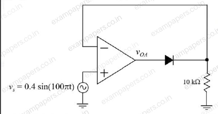
Log in to check the answer
You can attempt this question now. Sign in to view the answer key, explanations and discussion.Log in to check answerQuestion 15
Open questionINNAT1 markNeeds review
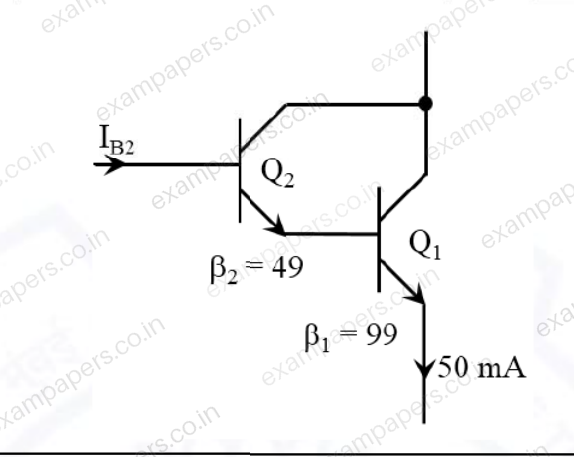
The transistor Q₁ has a current gain
and the transistor Q₂ has a current gain
. The current
in microampere is ______.
Log in to check the answer
You can attempt this question now. Sign in to view the answer key, explanations and discussion.Log in to check answerQuestion 30
Open questionINMCQ2 marksNeeds review
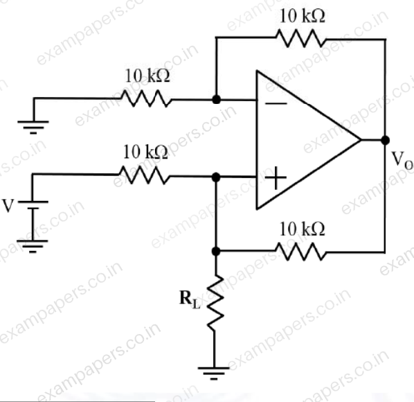
The output
of the ideal OpAmp used in the circuit shown below is 5 V. Then the value of resistor
in kilo ohm (k
) is
Your answerChoose one option.
Log in to check the answer
You can attempt this question now. Sign in to view the answer key, explanations and discussion.Log in to check answerQuestion 33
Open questionINMCQ2 marksNeeds review
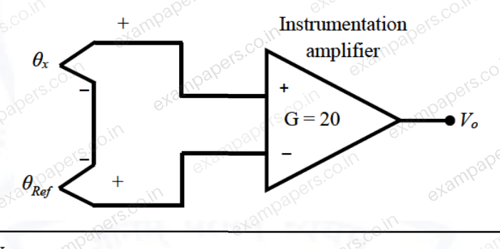
A J-type thermocouple has an output voltage
V, where
is the junction temperature in Celsius (°C). The thermocouple is used with reference junction compensation, as shown in the figure. The Instrumentation amplifier used has a gain G = 20. If
is 1 °C, for an input
of 100 °C, the output
of the instrumentation amplifier in millivolt is
Your answerChoose one option.
Log in to check the answer
You can attempt this question now. Sign in to view the answer key, explanations and discussion.Log in to check answerQuestion 47
Open questionINNAT2 marksNeeds review
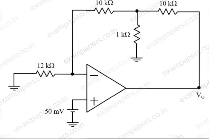
The circuit shown below uses an ideal OpAmp. Output
in volt is ______ (rounded off to one decimal place).
Log in to check the answer
You can attempt this question now. Sign in to view the answer key, explanations and discussion.Log in to check answerQuestion 48
Open questionINNAT2 marksNeeds review
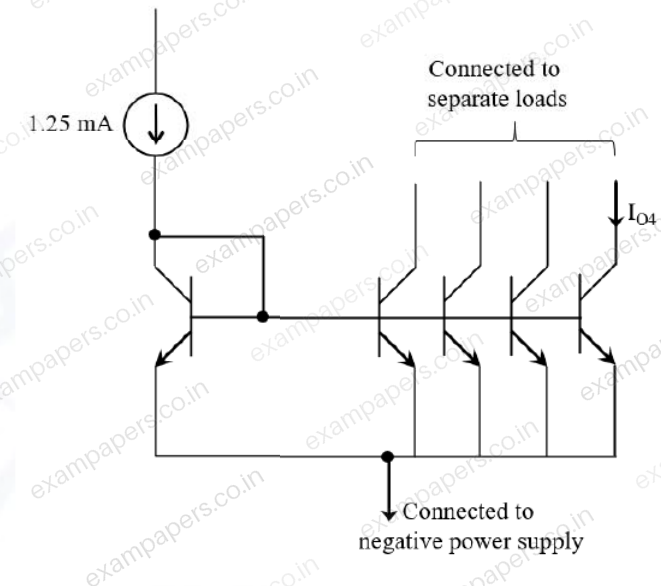
All the transistors used in the circuit are matched and have a current gain
of 20. Neglecting the Early effect, the current
in milliampere is _____.
Log in to check the answer
You can attempt this question now. Sign in to view the answer key, explanations and discussion.Log in to check answerQuestion 7
Open questionINMCQ1 markNeeds review
If the diodes in the circuit shown are ideal and the breakdown voltage
of the Zener diode is 5 V, the power dissipated in the 100
resistor (in watts) is ____. 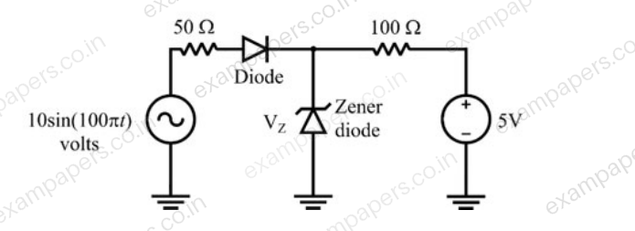
Your answerChoose one option.
Log in to check the answer
You can attempt this question now. Sign in to view the answer key, explanations and discussion.Log in to check answerQuestion 17
Open questionINNAT1 markNeeds review
Assuming ideal opamps, the output voltage at
in the figure shown (in volts) is ____. 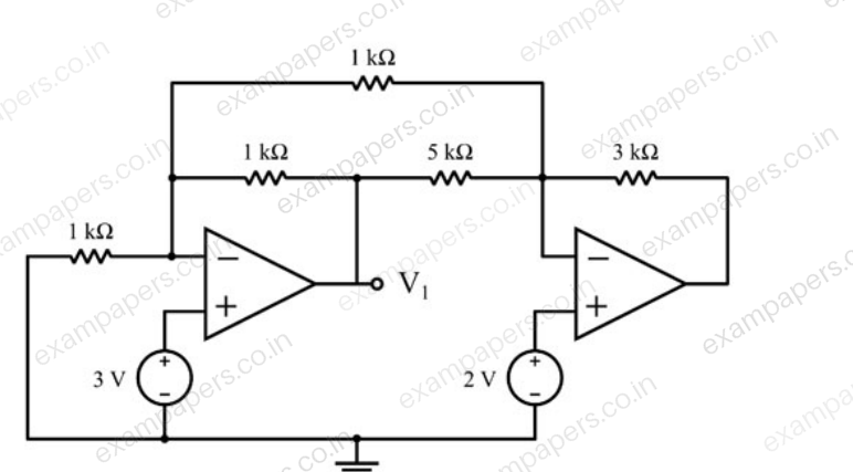
Log in to check the answer
You can attempt this question now. Sign in to view the answer key, explanations and discussion.Log in to check answerQuestion 21
Open questionINNAT1 markNeeds review
Assume that the opamp in the circuit shown is ideal. The value of
(in k
) is ____. 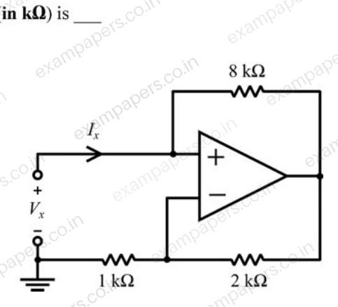
Log in to check the answer
You can attempt this question now. Sign in to view the answer key, explanations and discussion.Log in to check answerQuestion 39
Open questionINNAT2 marksNeeds review
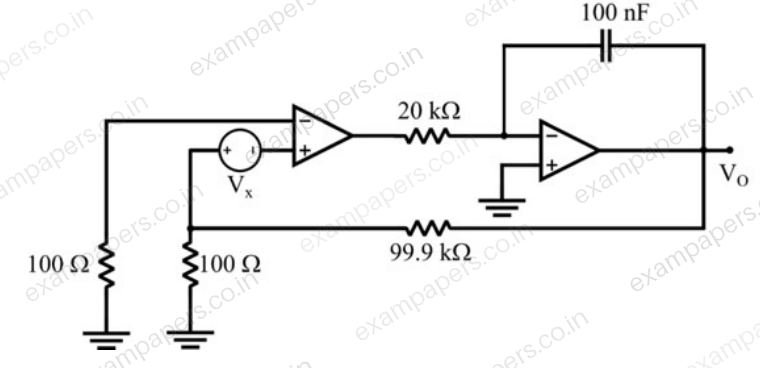
If the opamps in the circuit shown are ideal and
mV, the steady state value of
(in volts, rounded off to two decimal places) is ____
Log in to check the answer
You can attempt this question now. Sign in to view the answer key, explanations and discussion.Log in to check answer