
Instrumentation Engineering
GATE IN topic:analog-electronics PYQs
Build your understanding with focused practice from past exam papers.
Questions 41–50 of 65. Imported answers require independent review unless marked reviewed.
Question 49
Open questionINNAT2 marksNeeds review
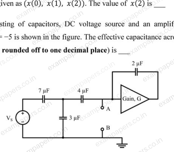
A circuit consisting of capacitors, DC voltage source and an amplifier having a voltage gain
is shown in the figure. The effective capacitance across the nodes A and B (in μF, rounded off to one decimal place) is ____
Log in to check the answer
You can attempt this question now. Sign in to view the answer key, explanations and discussion.Log in to check answerQuestion 51
Open questionINNAT2 marksNeeds review
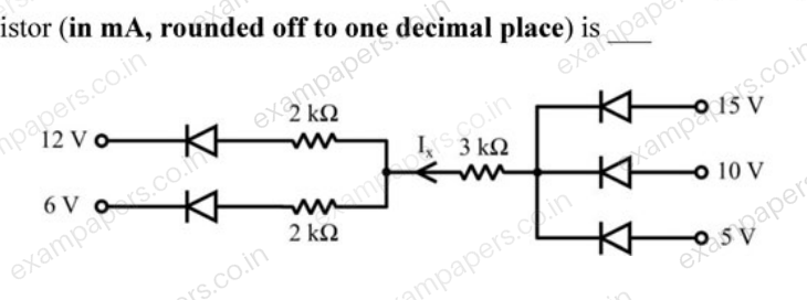
Assume the diodes in the circuit shown are ideal. The current
flowing through the 3 kΩ resistor (in mA, rounded off to one decimal place) is ____
Log in to check the answer
You can attempt this question now. Sign in to view the answer key, explanations and discussion.Log in to check answerQuestion 10
Open questionINMCQ1 markNeeds review
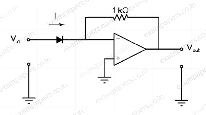
In the circuit shown below, the input voltage
is positive. The current (
) - voltage (
) characteristics of the diode can be assumed to be
under the forward bias condition, where
is the thermal voltage and
is the reverse saturation current. Assuming an ideal op-amp, the output voltage
of the circuit is proportional to
Your answerChoose one option.
Log in to check the answer
You can attempt this question now. Sign in to view the answer key, explanations and discussion.Log in to check answerQuestion 11
Open questionINMCQ1 markNeeds review
The correct biasing conditions for typical operation of light emitting diodes, photodiodes, Zener diodes are, respectively
Your answerChoose one option.
Log in to check the answer
You can attempt this question now. Sign in to view the answer key, explanations and discussion.Log in to check answerQuestion 33
Open questionINMCQ2 marksNeeds review
A voltage amplifier is constructed using enhancement mode MOSFETs labeled M1, M2, M3 and M4 in the figure below. M1, M2 and M4 are n-channel MOSFETs and M3 is a p-channel MOSFET. All MOSFETs operate in saturation mode and channel length modulation can be ignored. The low frequency, small signal input and output voltages are
and
respectively and the dc power supply voltage is
. All n-channel MOSFETs have identical transconductance
while the p-channel MOSFET has transconductance
. The expressions for the low frequency small signal voltage gain
is 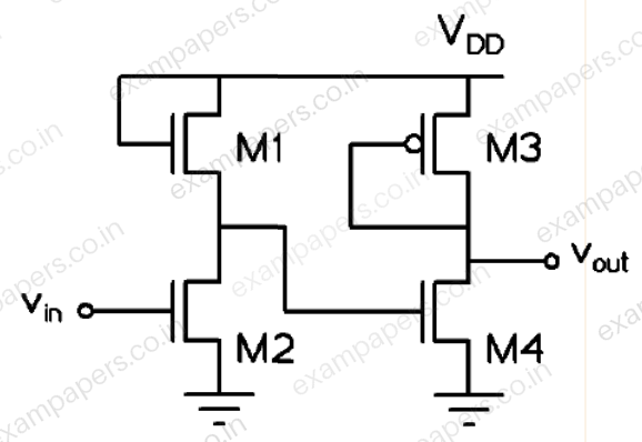
Your answerChoose one option.
Log in to check the answer
You can attempt this question now. Sign in to view the answer key, explanations and discussion.Log in to check answerQuestion 34
Open questionINMCQ2 marksNeeds review
In the circuit shown below, assume that the comparators are ideal and all components have zero propagation delay. In one period of the input signal
, the fraction of the time for which the output OUT is in logic state HIGH is 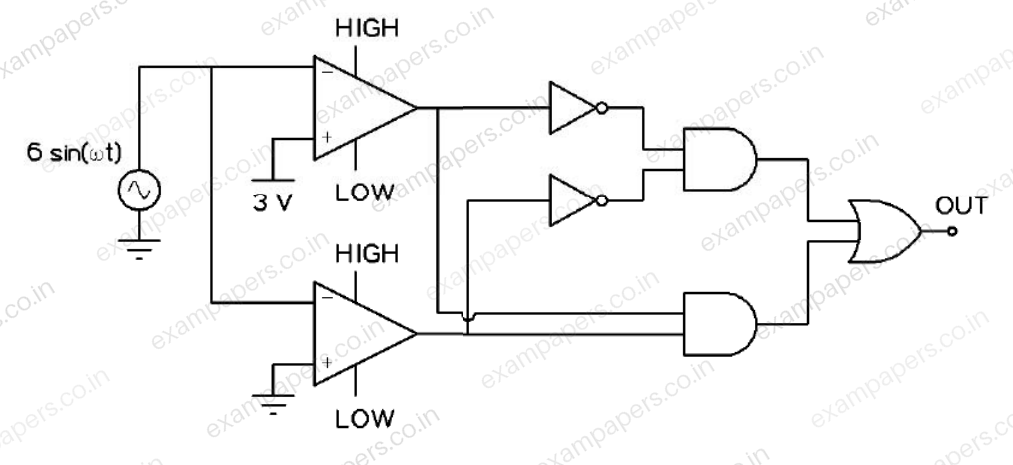
Your answerChoose one option.
Log in to check the answer
You can attempt this question now. Sign in to view the answer key, explanations and discussion.Log in to check answerQuestion 50
Open questionINNAT2 marksNeeds review
In the circuit shown below, all transistors are n-channel enhancement mode MOSFETs. They are identical and are biased to operate in saturation mode. Ignoring channel length modulation, the output voltage
is ______ V.
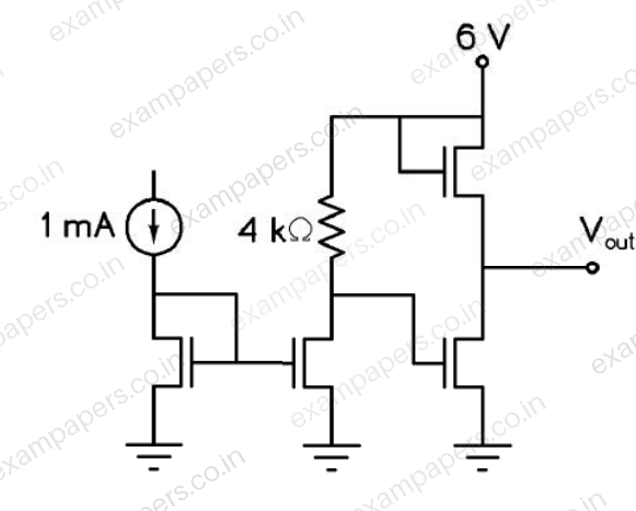
Log in to check the answer
You can attempt this question now. Sign in to view the answer key, explanations and discussion.Log in to check answerQuestion 51
Open questionINNAT2 marksNeeds review
In the circuit shown below, all OPAMPS are ideal. The current
A when the resistance
______ kΩ.
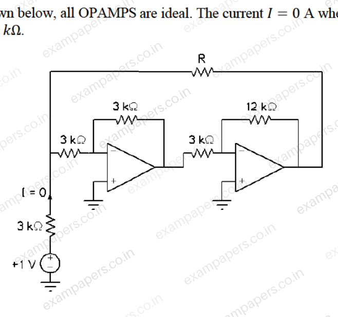
Log in to check the answer
You can attempt this question now. Sign in to view the answer key, explanations and discussion.Log in to check answerQuestion 15
Open questionINNAT1 markNeeds review
In the given circuit, assume that the opamp is ideal and the transistor has a
of 20. The current
(in
A) flowing through the load
is _____.
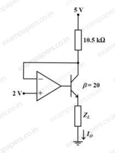
Log in to check the answer
You can attempt this question now. Sign in to view the answer key, explanations and discussion.Log in to check answerQuestion 16
Open questionINNAT1 markNeeds review
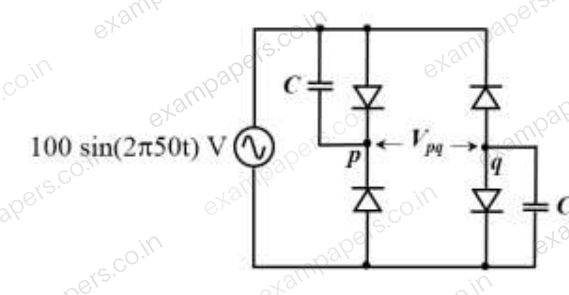
The diodes given in the circuit are ideal. At
ms,
(in Volts) is _____.
Log in to check the answer
You can attempt this question now. Sign in to view the answer key, explanations and discussion.Log in to check answer