
Instrumentation Engineering
GATE IN topic:measurement PYQs
Build your understanding with focused practice from past exam papers.
Questions 181–190 of 650. Imported answers require independent review unless marked reviewed.
Question 51
Open questionINNAT2 marksNeeds review
In the figure shown,
,
, and INA is assumed to be ideal. The equivalent resistance between A and B is ____ k
(rounded off to nearest integer). 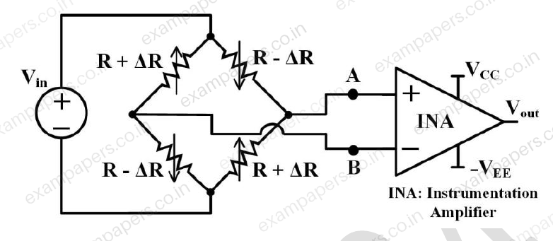
Log in to check the answer
You can attempt this question now. Sign in to view the answer key, explanations and discussion.Log in to check answerQuestion 52
Open questionINNAT2 marksNeeds review
Consider the capacitive sensor circuit and its output voltage shown in the figure. The circuit is switched ON at
. Assuming the opamp to be ideal, the frequency of the output voltage
is __________ kHz (rounded off to two decimal places). 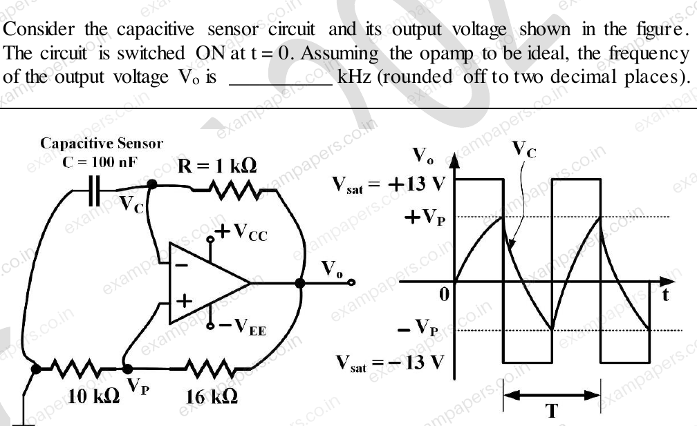
Log in to check the answer
You can attempt this question now. Sign in to view the answer key, explanations and discussion.Log in to check answerQuestion 53
Open questionINNAT2 marksNeeds review
The 4-point DFTs of two sequences x[n] and y[n] are X[k] = [1, −j, 1, j] and Y[k] = [1, 3j, 1, −3j], respectively. Assuming z[n] represents the 4-point circular convolution of x[n] and y[n], the value of z[0] is ________ (rounded off to nearest integer).
Note: The DFT of an N-point sequence x[n] is defined as
Log in to check the answer
You can attempt this question now. Sign in to view the answer key, explanations and discussion.Log in to check answerQuestion 54
Open questionINNAT2 marksNeeds review
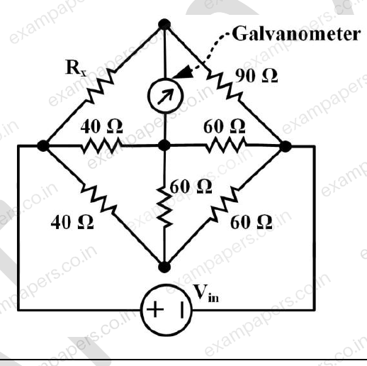
Consider the figure shown. For zero deflection in the galvanometer, the required value of resistor R_x is ____ Ω (rounded off to nearest integer).
Log in to check the answer
You can attempt this question now. Sign in to view the answer key, explanations and discussion.Log in to check answerQuestion 55
Open questionINNAT2 marksNeeds review
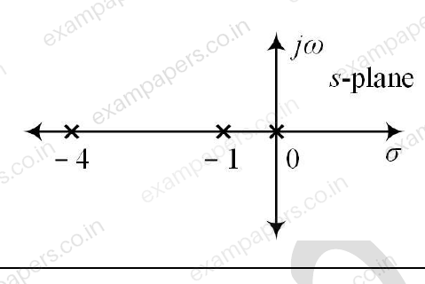
Consider a unity negative feedback system with its open-loop pole-zero map as shown in the figure. If the point s = jα, α > 0, lies on the root locus, the value of α is ________ (rounded off to nearest integer).
Note: The poles are marked with × in the figure.
Log in to check the answer
You can attempt this question now. Sign in to view the answer key, explanations and discussion.Log in to check answerQuestion 56
Open questionINNAT2 marksNeeds review
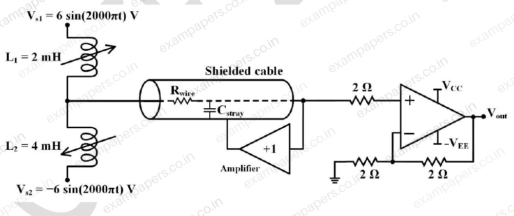
A shielded cable with C_stray = 20 pF and R_wire = 10 Ω is used to connect the inductive sensors as shown in the figure. The RMS value of V_out is ____ V (rounded off to two decimal places).
Note: Assume all components are ideal, and sensors are not magnetically coupled.
Log in to check the answer
You can attempt this question now. Sign in to view the answer key, explanations and discussion.Log in to check answerQuestion 57
Open questionINNAT2 marksNeeds review
In the figure shown, the diode current is given by
. V_D is the diode voltage in volts, T is the absolute temperature in Kelvin, α = 1.16 × 10⁴ K/V, and I_S = 10⁻¹⁵ A is the saturation current. The dc current source, opamp and the resistors are ideal, and are assumed to be temperature independent. The change in the output voltage (V_out) per Kelvin change in temperature is ________ mV (rounded off to one decimal place). 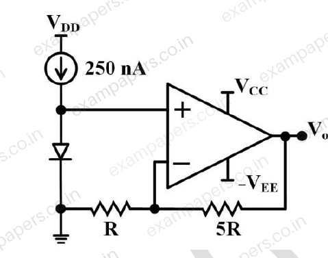
Log in to check the answer
You can attempt this question now. Sign in to view the answer key, explanations and discussion.Log in to check answerQuestion 58
Open questionINNAT2 marksNeeds review
An ADC has a full scale voltage of 1.4 V, resolution of 200 mV, and produces binary output data. The input signal of the ADC has a bandwidth of 500 MHz, and it samples the data at the Nyquist rate. The parallel data output is converted to a serial bit stream using a parallel-to-serial converter. The data rate at the output of the parallel-to-serial converter is ____ Gbps (rounded off to nearest integer).
Log in to check the answer
You can attempt this question now. Sign in to view the answer key, explanations and discussion.Log in to check answerQuestion 59
Open questionINNAT2 marksNeeds review
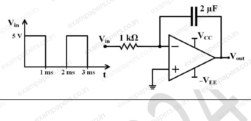
In the circuit shown, assume the opamp is ideal and the initial charge on the capacitor is zero. The output voltage at time t = 2 ms is ____ V (rounded off to one decimal place).
Log in to check the answer
You can attempt this question now. Sign in to view the answer key, explanations and discussion.Log in to check answerQuestion 60
Open questionINNAT2 marksNeeds review
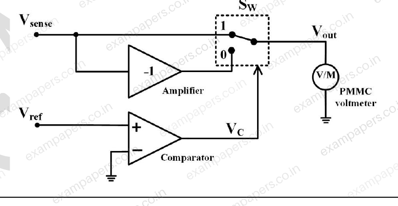
In the figure shown, S_W is a switch whose position changes from 1 to 0 when V_C changes from logic HIGH to LOW and vice versa. The bandwidth of the permanent magnet moving coil (PMC) type voltmeter is 1 Hz. If V_sense = 2 sin(4000πt) V and V_ref = 4 sin(2000πt) V, the voltmeter reading is ______ V (rounded off to nearest integer).
Note: Assume all components are ideal.
Log in to check the answer
You can attempt this question now. Sign in to view the answer key, explanations and discussion.Log in to check answer