
Mechanical Engineering
GATE ME topic:engineering-mechanics PYQs
Build your understanding with focused practice from past exam papers.
Questions 21–30 of 61. Imported answers require independent review unless marked reviewed.
Question 39
Open questionMEMCQ2 marksNeeds review
A rigid body in the X-Y plane consists of two point mass (1 kg each) attached to the ends of two massless rods, each of 1 cm length, as shown in the figure. It rotates at 30 RPM counter-clockwise about the Z-axis passing through point O. A point mass of
kg, attached to one end of a third massless rod, is used for balancing the body by attaching the free end of the rod to point O. The length of the third rod is ______ cm. 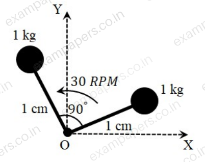
Your answerChoose one option.
Log in to check the answer
You can attempt this question now. Sign in to view the answer key, explanations and discussion.Log in to check answerQuestion 47
Open questionMEMSQ2 marksNeeds review
The lengths of members BC and CE in the frame shown in the figure are equal. All the members are rigid and lightweight, and the friction at the joints is negligible. Two forces of magnitude
are applied as shown, each at the mid-length of the respective member on which it acts. Which one or more of the following members do not carry any load (force)? 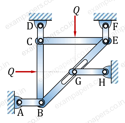
Your answerSelect all correct options. You can choose more than one.
Log in to check the answer
You can attempt this question now. Sign in to view the answer key, explanations and discussion.Log in to check answerQuestion 48
Open questionMENAT2 marksNeeds review
Consider two vectors:
Magnitude of the component of
orthogonal to
in the plane containing the vectors
and
is _________ (round off to 2 decimal places).Log in to check the answer
You can attempt this question now. Sign in to view the answer key, explanations and discussion.Log in to check answerQuestion 49
Open questionMENAT2 marksNeeds review
A structure, along with the loads applied on it, is shown in the figure. Self-weight of all the members is negligible and all the pin joints are friction-less. AE is a single member that contains pin C. Likewise, BE is a single member that contains pin D. Members GI and FH are overlapping rigid members. The magnitude of the force carried by member CI is ________ kN (in integer).
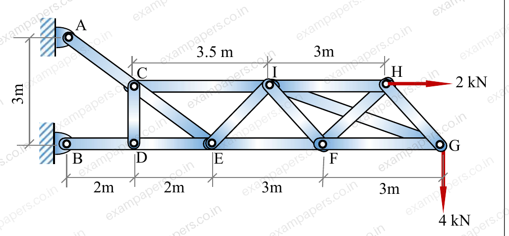
Log in to check the answer
You can attempt this question now. Sign in to view the answer key, explanations and discussion.Log in to check answerQuestion 50
Open questionMENAT2 marksNeeds review
Two rigid massless rods PR and RQ are joined at frictionless pin-joint R and are resting on ground at P and Q, respectively, as shown in the figure. A vertical force
acts on the pin R as shown. When the included angle
, the rods remain in static equilibrium due to Coulomb friction between the rods and ground at locations P and Q. At
, impending slip occurs simultaneously at points P and Q. Then the ratio of the coefficient of friction at Q to that at P (
) is _________ (round off to two decimal places). 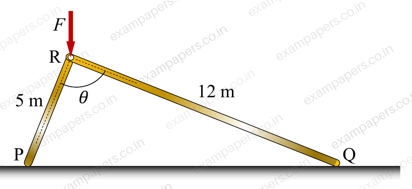
Log in to check the answer
You can attempt this question now. Sign in to view the answer key, explanations and discussion.Log in to check answerQuestion 51
Open questionMENAT2 marksNeeds review
A cylindrical disc of mass
kg and radius
m was spinning at
rad/s when it was placed on a flat horizontal surface and released (refer to the figure). Gravity
acts vertically downwards as shown in the figure. The coefficient of friction between the disc and the surface is finite and positive. Disregarding any other dissipation except that due to friction between the disc and the surface, the horizontal velocity of the center of the disc, when it starts rolling without slipping, will be ________ m/s (round off to 2 decimal places). 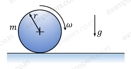
Log in to check the answer
You can attempt this question now. Sign in to view the answer key, explanations and discussion.Log in to check answerQuestion 14
Open questionMEMCQ1 markNeeds review
A plane truss
(
and
) is shown in the figure. The forces in the members
and
, respectively, are 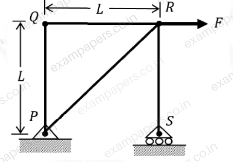
Your answerChoose one option.
Log in to check the answer
You can attempt this question now. Sign in to view the answer key, explanations and discussion.Log in to check answerQuestion 30
Open questionMEMCQ2 marksNeeds review
Consider a two degree of freedom system as shown in the figure, where
is a rigid uniform rod of length,
and mass,
. 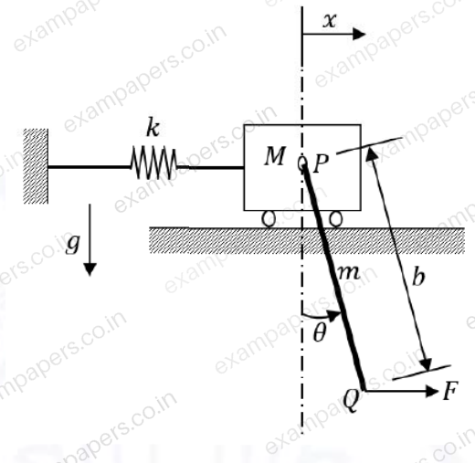
Assume that the spring deflects only horizontally and force
is applied horizontally at
. For this system, the Lagrangian,
isYour answerChoose one option.
Log in to check the answer
You can attempt this question now. Sign in to view the answer key, explanations and discussion.Log in to check answerQuestion 50
Open questionMENAT2 marksNeeds review
Two smooth identical spheres each of radius 125 mm and weight 100 N rest in a horizontal channel having vertical walls. The distance between vertical walls of the channel is 400 mm.
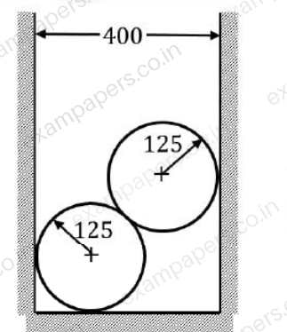
The reaction at the point of contact between two spheres is ______ N (round off to one decimal place).
Log in to check the answer
You can attempt this question now. Sign in to view the answer key, explanations and discussion.Log in to check answerQuestion 51
Open questionMENAT2 marksNeeds review
A block of negligible mass rests on a surface that is inclined at 30° to the horizontal plane as shown in the figure. When a vertical force of 900 N and a horizontal force of 750 N are applied, the block is just about to slide.
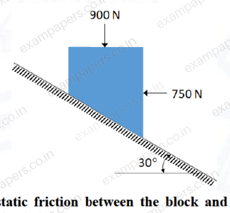
The coefficient of static friction between the block and surface is __________ (round off to two decimal places).
Log in to check the answer
You can attempt this question now. Sign in to view the answer key, explanations and discussion.Log in to check answer