
Physics
GATE PH Semiconductors in Equilibrium PYQs
Build your understanding with focused practice from past exam papers.
How to practice Semiconductors in Equilibrium
Attempt a question, record the concept and assumptions, then check the available answer. Rework mistakes after revising the relevant concepts. Topic tags can overlap; review the question context.
Questions 1–7 of 7. Imported answers require independent review unless marked reviewed.
Question 43
Open questionPHMCQ2 marksNeeds review
In the circuit shown,
Volts, where
is in seconds, which of the following options is correct?
(take the op amp to be ideal)
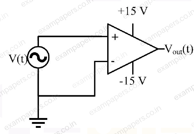
Your answerChoose one option.
Log in to check the answer
You can attempt this question now. Sign in to view the answer key, explanations and discussion.Log in to check answerQuestion 44
Open questionPHMCQ2 marksNeeds review
Considering the circuit and the associated signals measured at different pins (numbered as 1, 2, 3, 4, 5) shown in the figure, the correct option is
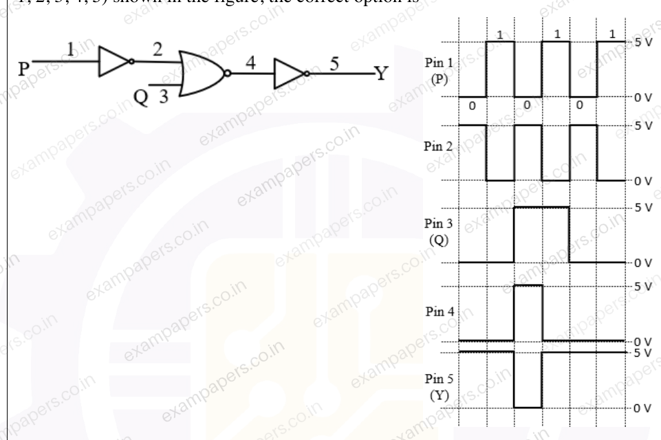
Your answerChoose one option.
Log in to check the answer
You can attempt this question now. Sign in to view the answer key, explanations and discussion.Log in to check answerQuestion 60
Open questionPHNAT2 marksNeeds review
The output signal (current
) of a reverse biased (with a voltage
) photodiode, on which light is incident, is fed to an amplifier (see figure). The output voltage is digitized by a 10 bit Analog to Digital converter (ADC) which has a reference voltage of 5 V. The smallest current
which can be measured by the circuit in nano-Amperes (rounded off to one decimal place) is _____. 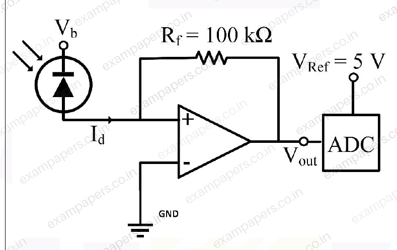
Log in to check the answer
You can attempt this question now. Sign in to view the answer key, explanations and discussion.Log in to check answerQuestion 19
Open questionPHMCQ1 markNeeds review
A logic gate circuit is shown in the figure below. The correct combination for the input
for which the output
is 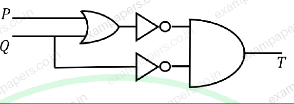
Your answerChoose one option.
Log in to check the answer
You can attempt this question now. Sign in to view the answer key, explanations and discussion.Log in to check answerQuestion 41
Open questionPHMCQ2 marksNeeds review
An
particle is scattered from an Au target at rest as shown in the figure.
and
are the detectors to detect the scattered
particle at an angle
and along the beam direction, respectively, as shown. The signals from
and
are converted to logic signals and fed to logic gates. When a particle is detected, the signal is 1 and is 0 otherwise. Which one of the following circuits detects the particle scattered at the angle
only? 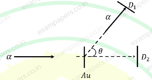
Your answerChoose one option.
Log in to check the answer
You can attempt this question now. Sign in to view the answer key, explanations and discussion.Log in to check answerQuestion 60
Open questionPHNAT2 marksNeeds review
In the transistor circuit shown in the figure,
and
. The value of the base current in
(rounded off to one decimal place) is ________ 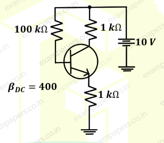
Log in to check the answer
You can attempt this question now. Sign in to view the answer key, explanations and discussion.Log in to check answerQuestion 65
Open questionPHNAT2 marksNeeds review
The figure shows an opamp circuit with a 5.1 V Zener diode in the feedback loop. The opamp runs from
V supplies. If a +1 V signal is applied at the input, the output voltage (rounded off to one decimal place) is _____. 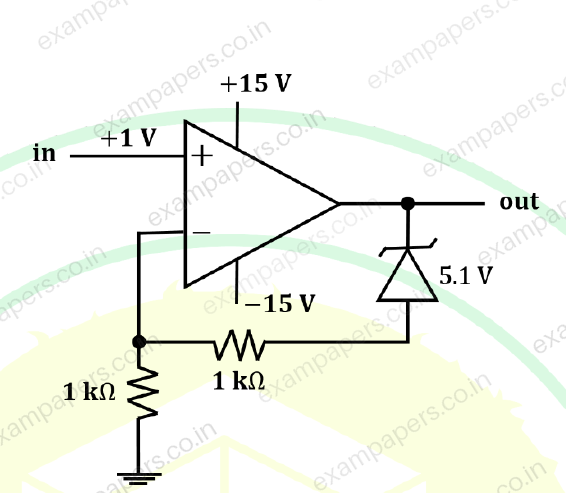
Log in to check the answer
You can attempt this question now. Sign in to view the answer key, explanations and discussion.Log in to check answer