
Engineering Sciences
GATE XE discipline:engineering-sciences PYQs
Build your understanding with focused practice from past exam papers.
Questions 1661–1670 of 1772. Imported answers require independent review unless marked reviewed.
Question 64
Open questionXE-DMCQ1 markNeeds review
A rectangular sheet ABCD of dimensions
and
along X and Y directions, respectively, is stretched to a rectangle AB′C′D′, as shown. The maximum principal strain (
) and minimum principal strain (
) due to the stretch are given by 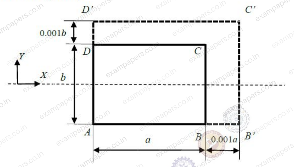
Your answerChoose one option.
Log in to check the answer
You can attempt this question now. Sign in to view the answer key, explanations and discussion.Log in to check answerQuestion 65
Open questionXE-DMCQ2 marksNeeds review
A solid bar of uniform square cross-section of side
and length
is rigidly fixed to the supports at the two ends. When the temperature in the rod is increased uniformly by
, the bar undergoes elastic buckling. Assume Young’s modulus
and coefficient of thermal expansion
to be independent of temperature. The coefficient of thermal expansion
is given byYour answerChoose one option.
Log in to check the answer
You can attempt this question now. Sign in to view the answer key, explanations and discussion.Log in to check answerQuestion 66
Open questionXE-DNAT2 marksNeeds review
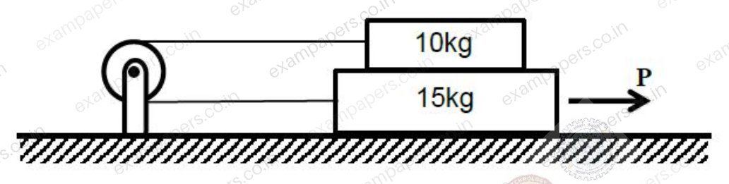
Two rigid blocks, of masses 10kg and 15kg, are arranged one on top of the other and placed on a horizontal rough surface as shown. The blocks are connected to each other through an inextensible cable passing over a frictionless pulley. The coefficients of static friction between the blocks and also between the bottom block and the surface are all equal to 0.3. The force
(in Newtons) needed to set the blocks in motion towards right is _________. (Assume acceleration due to gravity
). 
Log in to check the answer
You can attempt this question now. Sign in to view the answer key, explanations and discussion.Log in to check answerQuestion 67
Open questionXE-DNAT2 marksNeeds review
A truss system EFGH shown below is built using members EF, GH and FH of the same cross-sectional area 10mm² and member FG of cross-sectional area 20mm². The total strain energy stored (in Nm) in the system due to a force
acting at F is __________. Assume elastic deformations and members are made of steel with elastic modulus of 200GPa. 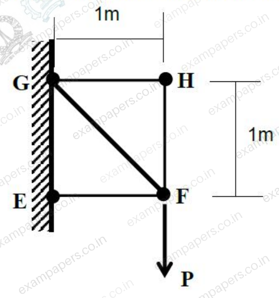
Log in to check the answer
You can attempt this question now. Sign in to view the answer key, explanations and discussion.Log in to check answerQuestion 68
Open questionXE-DNAT2 marksNeeds review
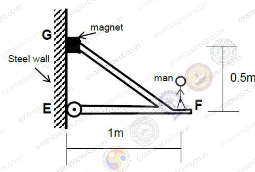
A rigid frame grips on to a steel wall as shown using a powerful magnet at the top support G and with a roller support at E. EF is horizontal. A man stands on the platform attached to the frame 1m away from the wall as shown. Assume the frame and magnet assembly to be of negligible weight and the mass of the man to be 80kg. The magnitude of the reaction (in Newtons) exerted by the frame onto the steel wall due to the weight of the man is __________. The magnetic force of attraction of the magnet at no load condition is 1kN. Magnet can be assumed to be small enough that it offers negligible moment resistance. Assume acceleration due to gravity,
. 
Log in to check the answer
You can attempt this question now. Sign in to view the answer key, explanations and discussion.Log in to check answerQuestion 69
Open questionXE-DNAT2 marksNeeds review
A manually operated band brake has a control lever EFG as shown and has a coefficient of kinetic friction equal to 0.2. The cylinder initially rotates clockwise at a constant frequency of 10 revolutions per second. A force P = 300N is applied at G. The pin support at O is frictionless. The radius of the cylinder is
and the radius of gyration is 0.1m. The mass of the cylinder is 50kg. Assume acceleration due to gravity
. The time required (in seconds) to reduce the rotational frequency to 5 revolutions per second is __________. 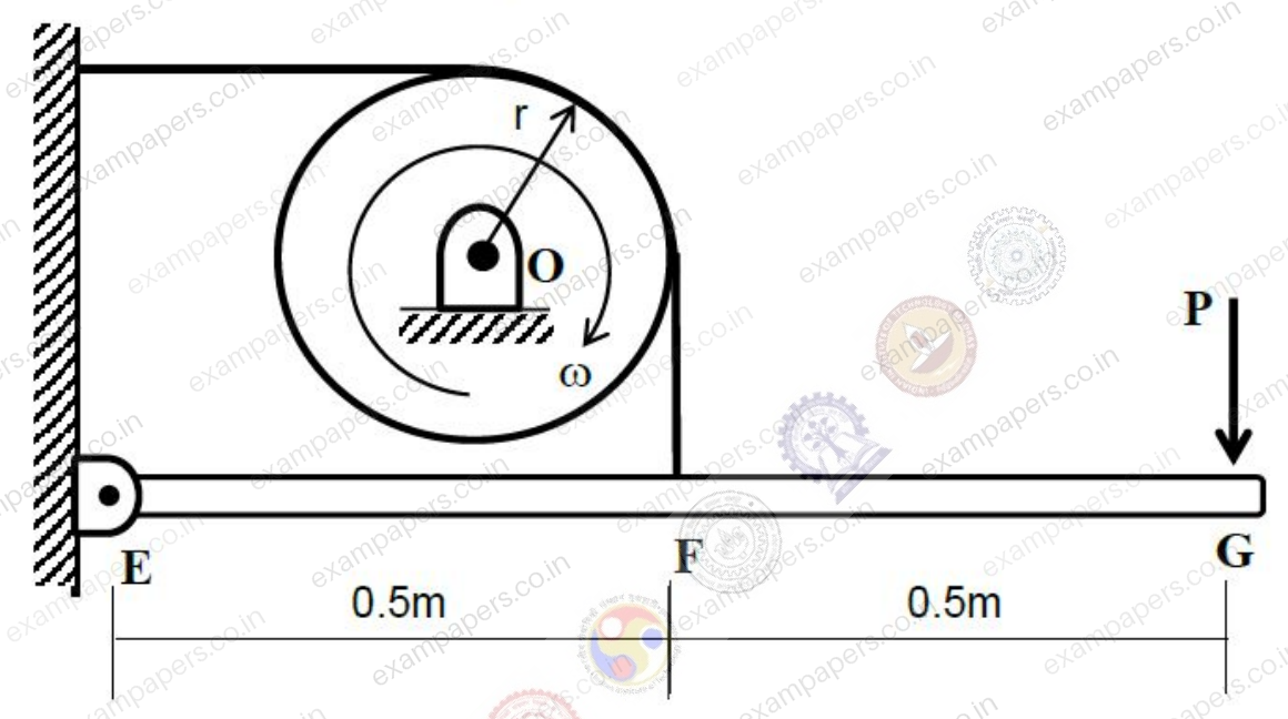
Log in to check the answer
You can attempt this question now. Sign in to view the answer key, explanations and discussion.Log in to check answerQuestion 70
Open questionXE-DNAT2 marksNeeds review
In a pin-connected mechanism shown, load P applied at F is 50N. Neglect the weight of the links and assume
for the spring. The bars EH and FG are pinned at O at their centre such that the lengths of EO, GO, HO and FO are all equal to
. The spring between G and H is unstretched when
. The angle
(in degrees) under equilibrium is __________. 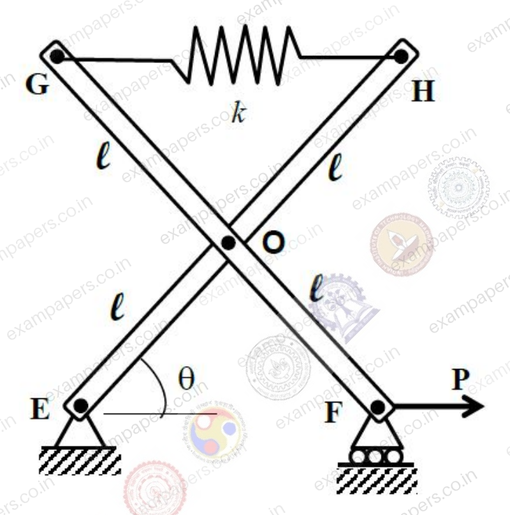
Log in to check the answer
You can attempt this question now. Sign in to view the answer key, explanations and discussion.Log in to check answerQuestion 71
Open questionXE-DNAT2 marksNeeds review
The frame shown below carries a vertical load
at its free end D. The frame is fixed at A and has a roller support at B. Magnitude of the reaction force at B (in kN) is __________. Assume that the effect of the axial force on bending is negligible. 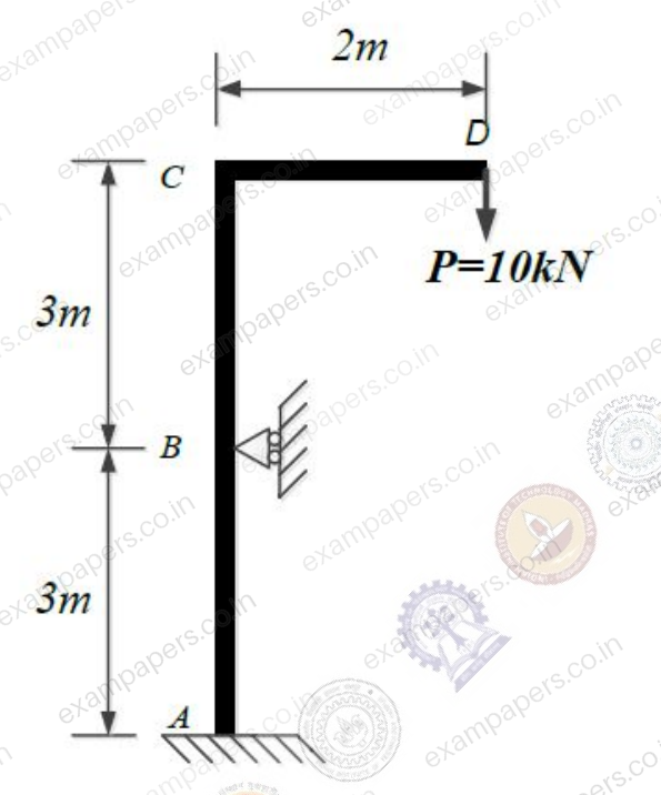
Log in to check the answer
You can attempt this question now. Sign in to view the answer key, explanations and discussion.Log in to check answerQuestion 72
Open questionXE-DNAT2 marksNeeds review
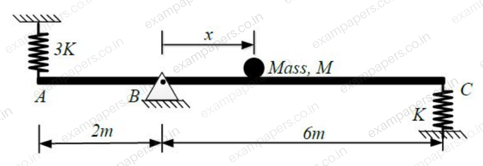
Consider the system shown below. Mass
is fixed to the rod AC at a distance
from the hinge point at B. Two springs of stiffness 3K and K are attached to the rod at points A and C, respectively. The natural frequency of angular oscillation of the system about B is 20 rad/s. Assume the rod to be rigid and massless. Magnitude of
(in metres) is __________. (
, and
). 
Log in to check the answer
You can attempt this question now. Sign in to view the answer key, explanations and discussion.Log in to check answerQuestion 73
Open questionXE-DMCQ2 marksNeeds review
The simply supported beam shown below is subjected to a clockwise moment
at point A and to counterclockwise moments
and
at points B and C, respectively. Which one of the following is the correct bending moment diagram (tensile at bottom is positive moment) for the beam? 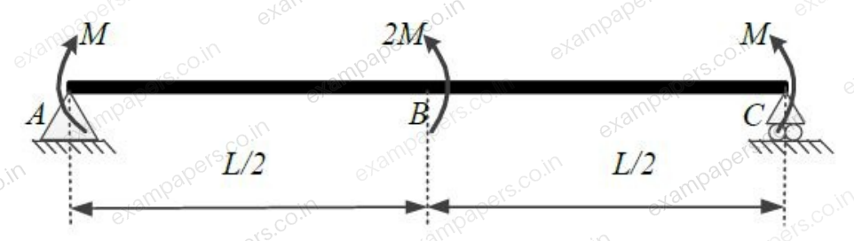
Your answerChoose one option.
Log in to check the answer
You can attempt this question now. Sign in to view the answer key, explanations and discussion.Log in to check answer