
GATE AE · 2026 · AE
Question 38: Engine Performance
Give it a try, then reveal the answer to check your work.
Question 38
AEMCQ2 marksNeeds review
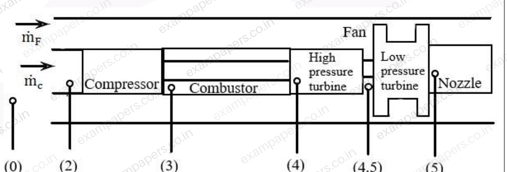
In an ideal turbofan engine shown in the figure below, the compressor is driven by the high pressure turbine, and the fan is driven by the low pressure turbine. The stations 0, 2, 3, 4, 4.5 and 5 refer to free-stream, compressor inlet, compressor outlet, combustor exit, high pressure turbine exit, and low pressure turbine exit, respectively, and the subscript ‘t’ refers to the total condition. Also,
,
and
. The total temperature ratio of the high pressure turbine (
) is given by ______.
Your answerChoose one option.
Log in to check the answer
You can attempt this question now. Sign in to view the answer key, explanations and discussion.Log in to check answerEXPLORE & PRACTISE
Paper and topic context
See where this question comes from and choose what to practise next.
2026AE
GATE AE 2026 · Paper 1
Aerospace Engineering · Original paper archive
- Section
- Aerospace Engineering
- Question type
- Multiple choice (MCQ)
- Marks
- 2 marks
Practise related topics
Explore more previous year questions using this question’s imported topic tags.
aerospace engineering
GATE AE previous year questions
aerodynamics
GATE AE previous year questions
flight mechanics
GATE AE previous year questions
engine performance
GATE AE previous year questions
Comments
Ask a question, share your approach, or help someone understand.
Log in to view the discussion
You’re not logged in. Log in or create an account to see discussions and add comments.