
Electrical Engineering
GATE EE concept:voltage PYQs
Build your understanding with focused practice from past exam papers.
Questions 51–60 of 61. Imported answers require independent review unless marked reviewed.
Question 11
Open questionEE-2MCQ1 markNeeds review
A phase-controlled, single-phase, full-bridge converter is supplying a highly inductive DC load. The converter is fed from a 230 V, 50 Hz, AC source. The fundamental frequency in Hz of the voltage ripple on the DC side is
Your answerChoose one option.
Log in to check the answer
You can attempt this question now. Sign in to view the answer key, explanations and discussion.Log in to check answerQuestion 13
Open questionEE-2MCQ1 markNeeds review
A three-phase voltage source inverter with ideal devices operating in 180° conduction mode is feeding a balanced star-connected resistive load. The DC voltage input is
. The peak of the fundamental component of the phase voltage isYour answerChoose one option.
Log in to check the answer
You can attempt this question now. Sign in to view the answer key, explanations and discussion.Log in to check answerQuestion 16
Open questionEE-2NAT1 markNeeds review
The figure below shows the circuit diagram of a controlled rectifier supplied from a 230 V, 50 Hz, 1-phase voltage source and a 10:1 ideal transformer. Assume that all devices are ideal. The firing angles of the thyristors
and
are 90° and 270°, respectively. 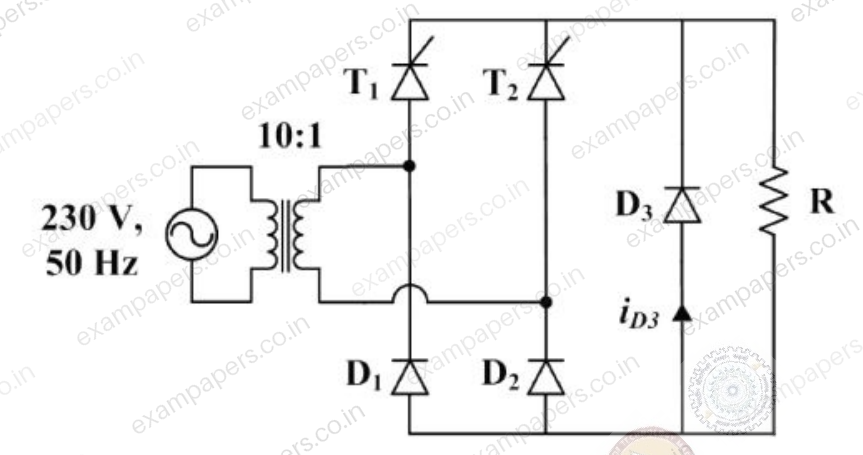
The RMS value of the current through diode
in amperes is _________.Log in to check the answer
You can attempt this question now. Sign in to view the answer key, explanations and discussion.Log in to check answerQuestion 21
Open questionEENAT1 markNeeds review
A 10-bus power system consists of four generator buses indexed as G1, G2, G3, G4 and six load buses indexed as L1, L2, L3, L4, L5, L6. The generator-bus G1 is considered as slack bus, and the load buses L3 and L4 are voltage controlled buses. The generator at bus G2 cannot supply the required reactive power demand, and hence it is operating at its maximum reactive power limit. The number of non-linear equations required for solving the load flow problem using Newton-Raphson method in polar form is _____.
Log in to check the answer
You can attempt this question now. Sign in to view the answer key, explanations and discussion.Log in to check answerQuestion 24
Open questionEENAT1 markNeeds review
In the converter circuit shown below, the switches are controlled such that the load voltage
is a 400 Hz square wave.
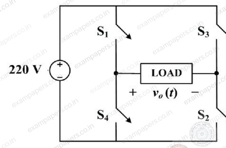
The RMS value of the fundamental component of
in volts is ________.Log in to check the answer
You can attempt this question now. Sign in to view the answer key, explanations and discussion.Log in to check answerQuestion 25
Open questionEENAT1 markNeeds review
A 3-phase voltage source inverter is supplied from a 600 V DC source as shown in the figure below.
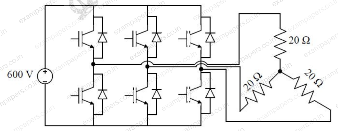
For a star connected resistive load of 20 Ω per phase, the load power for 120° device conduction, in kW, is ________.
Log in to check the answer
You can attempt this question now. Sign in to view the answer key, explanations and discussion.Log in to check answerQuestion 38
Open questionEEMCQ2 marksNeeds review
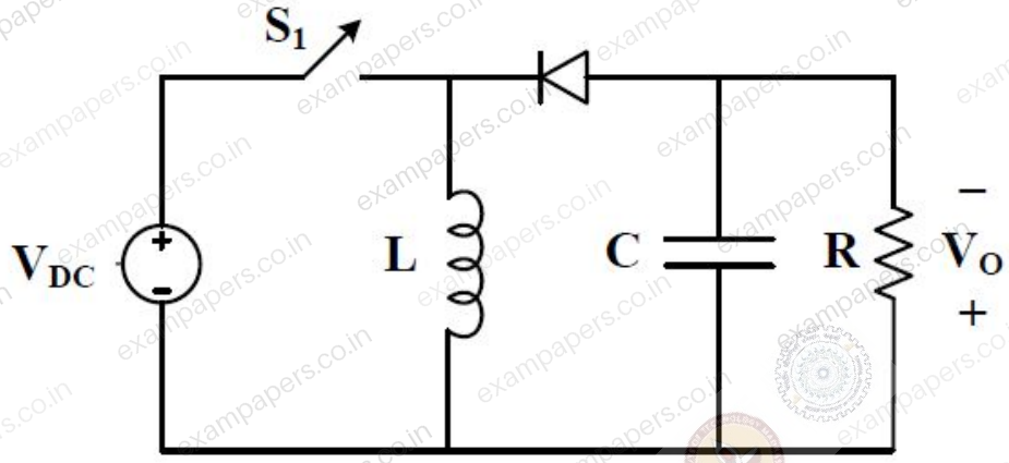
The input voltage V_DC of the buck-boost converter shown below varies from 32 V to 72 V. Assume that all components are ideal, inductor current is continuous, and output voltage is ripple free. The range of duty ratio D of the converter for which the magnitude of the steady-state output voltage remains constant at 48 V is
Your answerChoose one option.
Log in to check the answer
You can attempt this question now. Sign in to view the answer key, explanations and discussion.Log in to check answerQuestion 39
Open questionEE-2MCQ2 marksNeeds review
The figure below shows a half-bridge voltage source inverter supplying an RL-load with
and
. The desired fundamental frequency of the load voltage is 50 Hz. The switch control signals of the converter are generated using sinusoidal pulse width modulation with modulation index,
. At 50 Hz, the RL-load draws an active power of 1.44 kW. The value of DC source voltage
in volts is 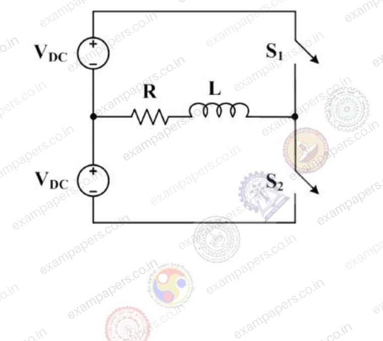
Your answerChoose one option.
Log in to check the answer
You can attempt this question now. Sign in to view the answer key, explanations and discussion.Log in to check answerQuestion 50
Open questionEE-2NAT2 marksNeeds review
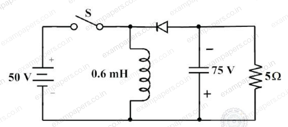
In the circuit shown all elements are ideal and the switch S is operated at 10 kHz and 60% duty ratio. The capacitor is large enough so that the ripple across it is negligible and at steady state acquires a voltage as shown. The peak current in amperes drawn from the 50 V DC source is _____. (Give the answer up to one decimal place.)
Log in to check the answer
You can attempt this question now. Sign in to view the answer key, explanations and discussion.Log in to check answerQuestion 52
Open questionEE-2NAT2 marksNeeds review
A 3-phase, 50 Hz generator supplies power of 3MW at 17.32 kV to a balanced 3-phase inductive load through an overhead line. The per phase line resistance and reactance are 0.25 Ω and 3.925Ω respectively. If the voltage at the generator terminal is 17.87 kV, the power factor of the load is _____.
Log in to check the answer
You can attempt this question now. Sign in to view the answer key, explanations and discussion.Log in to check answer