
GATE EE · 2017 · EE-2
Question 16: Power Electronics
Give it a try, then reveal the answer to check your work.
Question 16
EE-2NAT1 markNeeds review
The figure below shows the circuit diagram of a controlled rectifier supplied from a 230 V, 50 Hz, 1-phase voltage source and a 10:1 ideal transformer. Assume that all devices are ideal. The firing angles of the thyristors
and
are 90° and 270°, respectively. 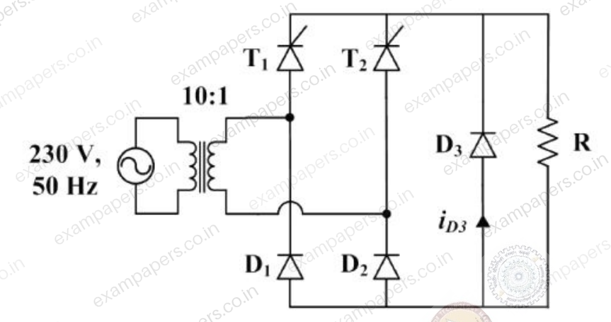
The RMS value of the current through diode
in amperes is _________.Log in to check the answer
You can attempt this question now. Sign in to view the answer key, explanations and discussion.Log in to check answerEXPLORE & PRACTISE
Paper and topic context
See where this question comes from and choose what to practise next.
2017EE-2
GATE EE 2017 · Paper 2
Electrical Engineering · Original paper archive
- Section
- Section EE-2
- Question type
- Numerical answer (NAT)
- Marks
- 1 mark
Practise related topics
Explore more previous year questions using this question’s imported topic tags.
electrical engineering
GATE EE previous year questions
electrical power
GATE EE previous year questions
electrical machines
GATE EE previous year questions
power electronics
GATE EE previous year questions
voltage
GATE EE previous year questions
Comments
Ask a question, share your approach, or help someone understand.
Log in to view the discussion
You’re not logged in. Log in or create an account to see discussions and add comments.